SL811HS
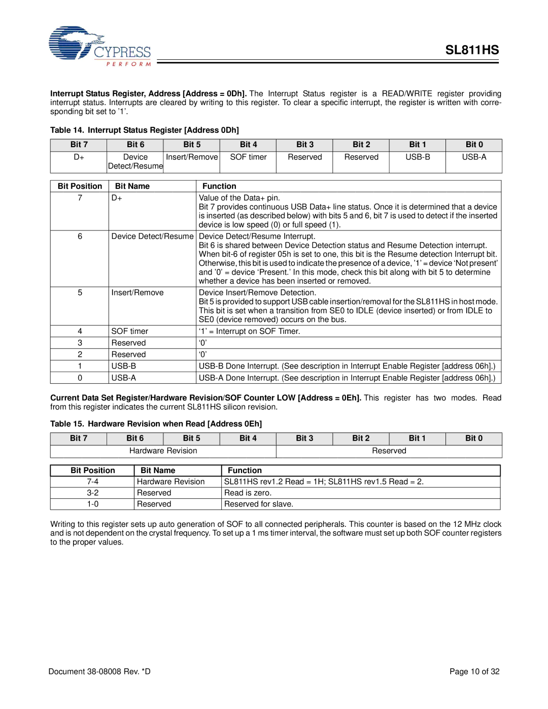
Interrupt Status Register, Address [Address = 0Dh]. The Interrupt Status register is a READ/WRITE register providing interrupt status. Interrupts are cleared by writing to this register. To clear a specific interrupt, the register is written with corre- sponding bit set to ’1’.
Table 14. Interrupt Status Register [Address 0Dh]
Bit 7 |
| Bit 6 |
| Bit 5 | Bit 4 |
| Bit 3 |
| Bit 2 | Bit 1 | Bit 0 | |
D+ |
| Device |
| Insert/Remove | SOF timer |
| Reserved |
| Reserved |
| ||
| Detect/Resume |
|
|
|
|
|
|
|
|
|
| |
|
|
|
|
|
|
|
|
|
| |||
Bit Position |
| Bit Name |
| Function |
|
|
|
|
| |||
7 |
| D+ |
| Value of the Data+ pin. |
|
|
|
|
| |||
|
|
|
|
| Bit 7 provides continuous USB Data+ line status. Once it is determined that a device | |||||||
|
|
|
|
| is inserted (as described below) with bits 5 and 6, bit 7 is used to detect if the inserted | |||||||
|
|
|
|
| device is low speed (0) or full speed (1). |
|
|
| ||||
6 |
| Device Detect/Resume | Device Detect/Resume Interrupt. |
|
|
| ||||||
|
|
|
|
| Bit 6 is shared between Device Detection status and Resume Detection interrupt. | |||||||
|
|
|
|
| When | |||||||
|
|
|
|
| Otherwise, this bit is used to indicate the presence of a device, ’1’ = device ‘Not present’ | |||||||
|
|
|
|
| and ’0’ = device ‘Present.’ In this mode, check this bit along with bit 5 to determine | |||||||
|
|
|
|
| whether a device has been inserted or removed. |
|
| |||||
5 |
| Insert/Remove |
| Device Insert/Remove Detection. |
|
|
| |||||
|
|
|
|
| Bit 5 is provided to support USB cable insertion/removal for the SL811HS in host mode. | |||||||
|
|
|
|
| This bit is set when a transition from SE0 to IDLE (device inserted) or from IDLE to | |||||||
|
|
|
|
| SE0 (device removed) occurs on the bus. |
|
| |||||
4 |
| SOF timer |
| ‘1’ = Interrupt on SOF Timer. |
|
|
| |||||
3 |
| Reserved |
| ‘0’ |
|
|
|
|
|
|
| |
2 |
| Reserved |
| ‘0’ |
|
|
|
|
|
|
| |
1 |
|
|
| |||||||||
0 |
|
| ||||||||||
Current Data Set Register/Hardware Revision/SOF Counter LOW [Address = 0Eh]. This register has two modes. Read from this register indicates the current SL811HS silicon revision.
Table 15. Hardware Revision when Read [Address 0Eh]
Bit 7 | Bit 6 | Bit 5 | Bit 4 | Bit 3 | Bit 2 |
| Bit 1 | Bit 0 |
| Hardware | Revision |
|
|
| Reserved |
| |
|
|
|
|
|
|
|
|
|
Bit Position
Bit Name
Function
Hardware Revision | SL811HS rev1.2 Read = 1H; SL811HS rev1.5 Read = 2. | |
Reserved | Read is zero. | |
Reserved | Reserved for slave. |
Writing to this register sets up auto generation of SOF to all connected peripherals. This counter is based on the 12 MHz clock and is not dependent on the crystal frequency. To set up a 1 ms timer interval, the software must set up both SOF counter registers to the proper values.
Document | Page 10 of 32 |
