SL811HS
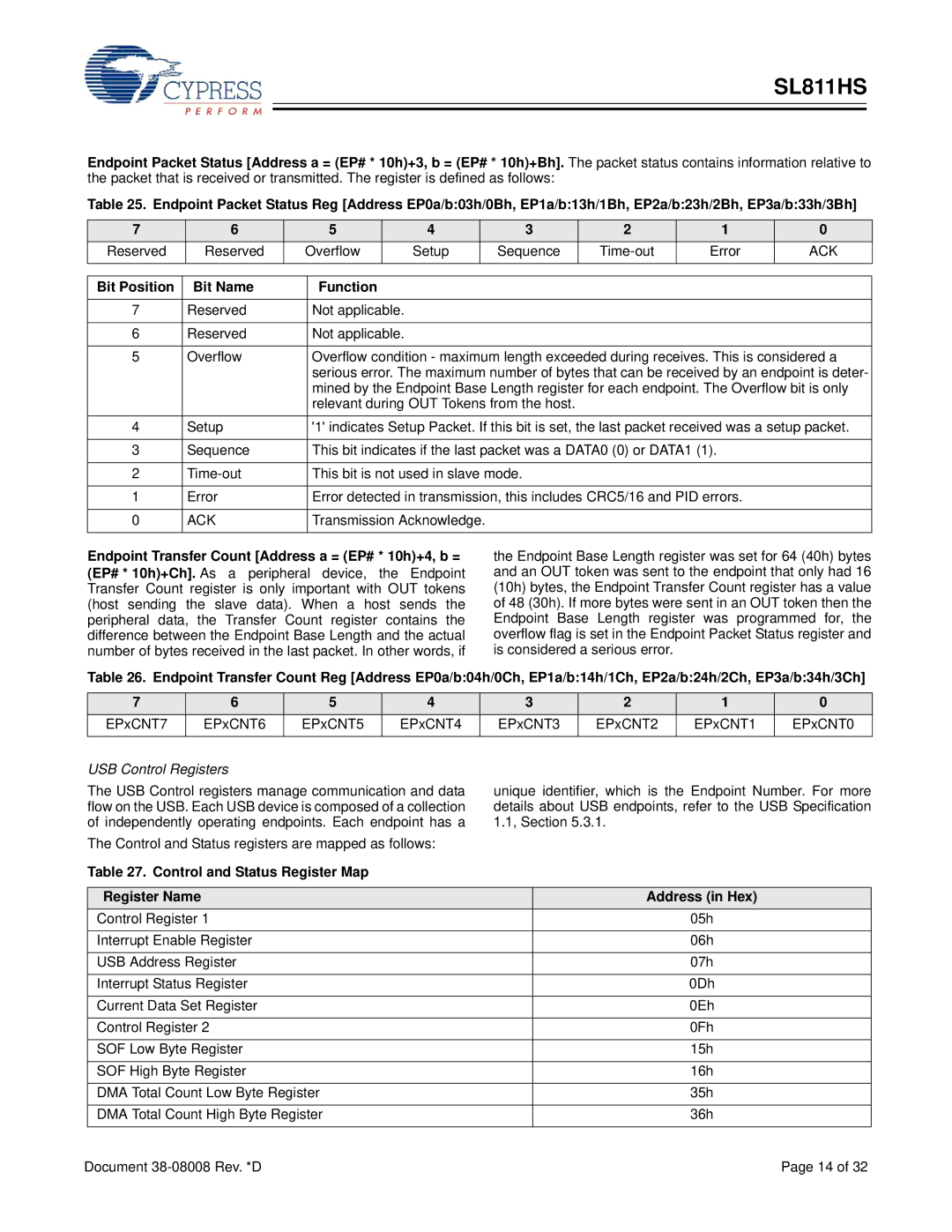
Endpoint Packet Status [Address a = (EP# * 10h)+3, b = (EP# * 10h)+Bh]. The packet status contains information relative to
the packet that is received or transmitted. The register is defined as follows:
Table 25. Endpoint Packet Status Reg [Address EP0a/b:03h/0Bh, EP1a/b:13h/1Bh, EP2a/b:23h/2Bh, EP3a/b:33h/3Bh]
7 | 6 | 5 |
| 4 |
| 3 | 2 | 1 | 0 | |
Reserved | Reserved | Overflow |
| Setup |
| Sequence | Error | ACK | ||
|
|
|
|
|
|
|
|
|
|
|
|
|
|
|
|
|
|
|
|
| |
Bit Position | Bit Name |
| Function |
|
|
|
|
|
| |
|
|
|
|
|
|
|
|
|
| |
7 | Reserved |
| Not applicable. |
|
|
|
|
|
| |
|
|
|
|
|
|
|
|
|
| |
6 | Reserved |
| Not applicable. |
|
|
|
|
|
| |
|
|
|
| |||||||
5 | Overflow |
| Overflow condition - maximum length exceeded during receives. This is considered a | |||||||
|
|
| serious error. The maximum number of bytes that can be received by an endpoint is deter- | |||||||
|
|
| mined by the Endpoint Base Length register for each endpoint. The Overflow bit is only | |||||||
|
|
| relevant during OUT Tokens from the host. |
|
|
| ||||
4 | Setup |
| '1' indicates Setup Packet. If this bit is set, the last packet received was a setup packet. | |||||||
|
|
|
|
| ||||||
3 | Sequence |
| This bit indicates if the last packet was a DATA0 (0) or DATA1 (1). |
| ||||||
|
|
|
|
|
|
| ||||
2 |
| This bit is not used in slave mode. |
|
|
| |||||
|
|
|
|
| ||||||
1 | Error |
| Error detected in transmission, this includes CRC5/16 and PID errors. |
| ||||||
|
|
|
|
|
|
|
| |||
0 | ACK |
| Transmission Acknowledge. |
|
|
|
| |||
|
|
|
|
|
|
|
|
|
|
|
Endpoint Transfer Count [Address a = (EP# * 10h)+4, b = (EP# * 10h)+Ch]. As a peripheral device, the Endpoint Transfer Count register is only important with OUT tokens (host sending the slave data). When a host sends the peripheral data, the Transfer Count register contains the difference between the Endpoint Base Length and the actual number of bytes received in the last packet. In other words, if
the Endpoint Base Length register was set for 64 (40h) bytes and an OUT token was sent to the endpoint that only had 16 (10h) bytes, the Endpoint Transfer Count register has a value of 48 (30h). If more bytes were sent in an OUT token then the Endpoint Base Length register was programmed for, the overflow flag is set in the Endpoint Packet Status register and is considered a serious error.
Table 26. Endpoint Transfer Count Reg [Address EP0a/b:04h/0Ch, EP1a/b:14h/1Ch, EP2a/b:24h/2Ch, EP3a/b:34h/3Ch]
7 | 6 | 5 | 4 | 3 | 2 | 1 | 0 |
EPxCNT7 | EPxCNT6 | EPxCNT5 | EPxCNT4 | EPxCNT3 | EPxCNT2 | EPxCNT1 | EPxCNT0 |
|
|
|
|
|
|
|
|
USB Control Registers
The USB Control registers manage communication and data flow on the USB. Each USB device is composed of a collection of independently operating endpoints. Each endpoint has a
The Control and Status registers are mapped as follows:
unique identifier, which is the Endpoint Number. For more details about USB endpoints, refer to the USB Specification 1.1, Section 5.3.1.
Table 27. Control and Status Register Map
| Register Name | Address (in Hex) |
| Control Register 1 | 05h |
|
|
|
| Interrupt Enable Register | 06h |
|
|
|
| USB Address Register | 07h |
|
|
|
| Interrupt Status Register | 0Dh |
|
|
|
| Current Data Set Register | 0Eh |
|
|
|
| Control Register 2 | 0Fh |
|
|
|
| SOF Low Byte Register | 15h |
|
|
|
| SOF High Byte Register | 16h |
|
|
|
| DMA Total Count Low Byte Register | 35h |
|
|
|
| DMA Total Count High Byte Register | 36h |
|
|
|
Document | Page 14 of 32 | |
