SL811HS
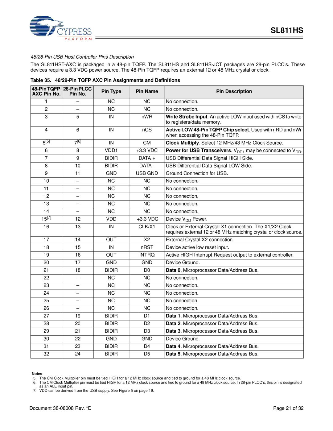
48/28-Pin USB Host Controller Pins Description
The
Table 35.
Pin Type | Pin Name | Pin Description | |||
AXC Pin No. | Pin No. | ||||
|
|
| |||
1 | – | NC | NC | No connection. | |
|
|
|
|
| |
2 | – | NC | NC | No connection. | |
|
|
|
|
| |
3 | 5 | IN | nWR | Write Strobe Input. An active LOW input used with nCS to write | |
|
|
|
| to registers/data memory. | |
4 | 6 | IN | nCS | Active LOW | |
|
|
|
| when accessing the | |
5[5] | 7[6] | IN | CM | Clock Multiply. Select 12 MHz/48 MHz Clock Source. | |
6 | 8 | VDD1 | +3.3 VDC | Power for USB Transceivers. VDD1 may be connected to VDD. | |
7 | 9 | BIDIR | DATA + | USB Differential Data Signal HIGH Side. | |
|
|
|
|
| |
8 | 10 | BIDIR | DATA - | USB Differential Data Signal LOW Side. | |
|
|
|
|
| |
9 | 11 | GND | USB GND | Ground Connection for USB. | |
|
|
|
|
| |
10 | – | NC | NC | No connection. | |
|
|
|
|
| |
11 | – | NC | NC | No connection. | |
|
|
|
|
| |
12 | – | NC | NC | No connection. | |
|
|
|
|
| |
13 | – | NC | NC | No connection. | |
|
|
|
|
| |
14 | – | NC | NC | No connection. | |
|
|
|
|
| |
15[7] | 12 | VDD | +3.3 VDC | Device VDD Power. | |
16 | 13 | IN | CLK/X1 | Clock or External Crystal X1 connection. The X1/X2 Clock | |
|
|
|
| requires external 12 or 48 MHz matching crystal or clock source. | |
17 | 14 | OUT | X2 | External Crystal X2 connection. | |
|
|
|
|
| |
18 | 15 | IN | nRST | Device active low reset input. | |
|
|
|
|
| |
19 | 16 | OUT | INTRQ | Active HIGH Interrupt Request output to external controller. | |
|
|
|
|
| |
20 | 17 | GND | GND | Device Ground. | |
|
|
|
|
| |
21 | 18 | BIDIR | D0 | Data 0. Microprocessor Data/Address Bus. | |
22 | – | NC | NC | No connection. | |
|
|
|
|
| |
23 | – | NC | NC | No connection. | |
|
|
|
|
| |
24 | – | NC | NC | No connection. | |
|
|
|
|
| |
25 | – | NC | NC | No connection. | |
|
|
|
|
| |
26 | – | NC | NC | No connection. | |
|
|
|
|
| |
27 | 19 | BIDIR | D1 | Data 1. Microprocessor Data/Address Bus. | |
28 | 20 | BIDIR | D2 | Data 2. Microprocessor Data/Address Bus. | |
|
|
|
|
| |
29 | 21 | BIDIR | D3 | Data 3. Microprocessor Data/Address Bus. | |
|
|
|
|
| |
30 | 22 | GND | GND | Device Ground. | |
|
|
|
|
| |
31 | 23 | BIDIR | D4 | Data 4. Microprocessor Data/Address Bus. | |
|
|
|
|
| |
32 | 24 | BIDIR | D5 | Data 5. Microprocessor Data/Address Bus. | |
|
|
|
|
|
Notes
5.The CM Clock Multiplier pin must be tied HIGH for a 12 MHz clock source and tied to ground for a 48 MHz clock source.
6.The CM Clock Multiplier pin must be tied HIGH for a 12 MHz clock source and tied to ground for a 48 MHz clock source. In
7.VDD can be derived from the USB supply. See Figure 5 on page 19.
Document | Page 21 of 32 |