SL811HS
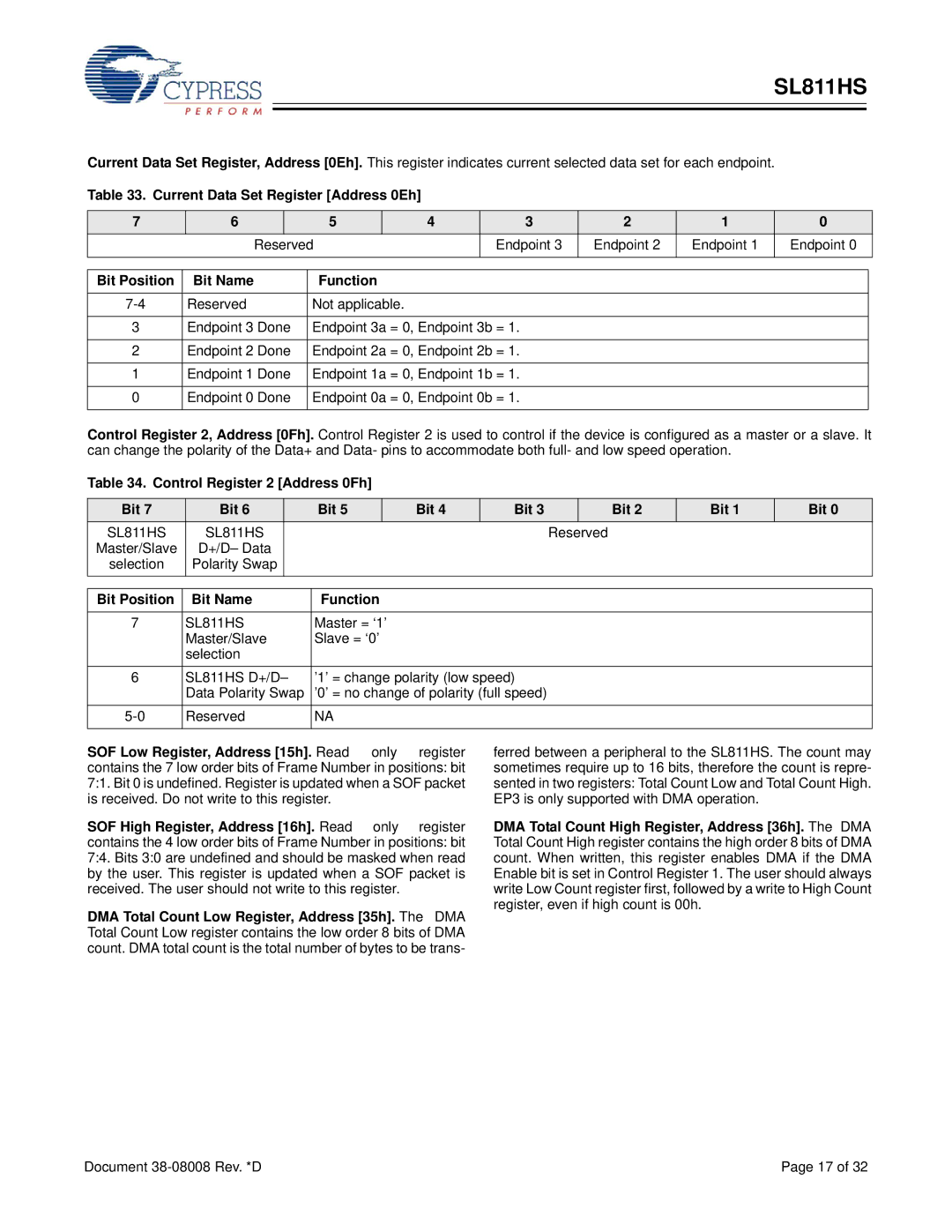
Current Data Set Register, Address [0Eh]. This register indicates current selected data set for each endpoint.
Table 33. Current Data Set Register [Address 0Eh]
7 | 6 |
| 5 |
| 4 | 3 | 2 | 1 | 0 |
| Reserved |
| Endpoint 3 | Endpoint 2 | Endpoint 1 | Endpoint 0 | |||
|
|
|
|
|
|
|
|
|
|
|
|
|
|
|
|
|
| ||
Bit Position | Bit Name | Function |
|
|
|
|
| ||
|
|
|
|
|
|
|
| ||
Reserved | Not applicable. |
|
|
|
|
| |||
|
|
|
|
|
| ||||
3 | Endpoint 3 Done | Endpoint 3a = 0, Endpoint 3b = 1. |
|
|
| ||||
|
|
|
|
|
| ||||
2 | Endpoint 2 Done | Endpoint 2a = 0, Endpoint 2b = 1. |
|
|
| ||||
|
|
|
|
|
| ||||
1 | Endpoint 1 Done | Endpoint 1a = 0, Endpoint 1b = 1. |
|
|
| ||||
|
|
|
|
|
| ||||
0 | Endpoint 0 Done | Endpoint 0a = 0, Endpoint 0b = 1. |
|
|
| ||||
|
|
|
|
|
|
|
|
|
|
Control Register 2, Address [0Fh]. Control Register 2 is used to control if the device is configured as a master or a slave. It can change the polarity of the Data+ and Data- pins to accommodate both full- and low speed operation.
Table 34. Control Register 2 [Address 0Fh]
Bit 7 | Bit 6 | Bit 5 | Bit 4 | Bit 3 |
| Bit 2 | Bit 1 | Bit 0 |
SL811HS | SL811HS |
|
|
| Reserved |
|
| |
Master/Slave | D+/D– Data |
|
|
|
|
|
|
|
selection | Polarity Swap |
|
|
|
|
|
|
|
Bit Position | Bit Name | Function |
|
|
|
7 | SL811HS | Master = ‘1’ |
| Master/Slave | Slave = ‘0’ |
| selection |
|
6 | SL811HS D+/D– | ’1’ = change polarity (low speed) |
| Data Polarity Swap | ’0’ = no change of polarity (full speed) |
Reserved | NA | |
|
|
|
SOF Low Register, Address [15h]. Read only register
contains the 7 low order bits of Frame Number in positions: bit 7:1. Bit 0 is undefined. Register is updated when a SOF packet is received. Do not write to this register.
SOF High Register, Address [16h]. Read only register contains the 4 low order bits of Frame Number in positions: bit 7:4. Bits 3:0 are undefined and should be masked when read by the user. This register is updated when a SOF packet is received. The user should not write to this register.
DMA Total Count Low Register, Address [35h]. The DMA Total Count Low register contains the low order 8 bits of DMA count. DMA total count is the total number of bytes to be trans-
ferred between a peripheral to the SL811HS. The count may sometimes require up to 16 bits, therefore the count is repre- sented in two registers: Total Count Low and Total Count High. EP3 is only supported with DMA operation.
DMA Total Count High Register, Address [36h]. The DMA Total Count High register contains the high order 8 bits of DMA count. When written, this register enables DMA if the DMA Enable bit is set in Control Register 1. The user should always write Low Count register first, followed by a write to High Count register, even if high count is 00h.
Document | Page 17 of 32 |
