DES-3226 NWay Standalone Fast Ethernet Switch User’s Guide
3
IDENTIFYING EXTERNAL COMPONENTS
This chapter describes the front panel, rear panel, side panels, optional
Front Panel
The front panel of the Switch consists of LED indicators, an
Figure 3-1. Front panel view of the Switch
•Comprehensive LED indicators display the status of the Switch and the network (see the LED Indicators section below).
•An
•A
•
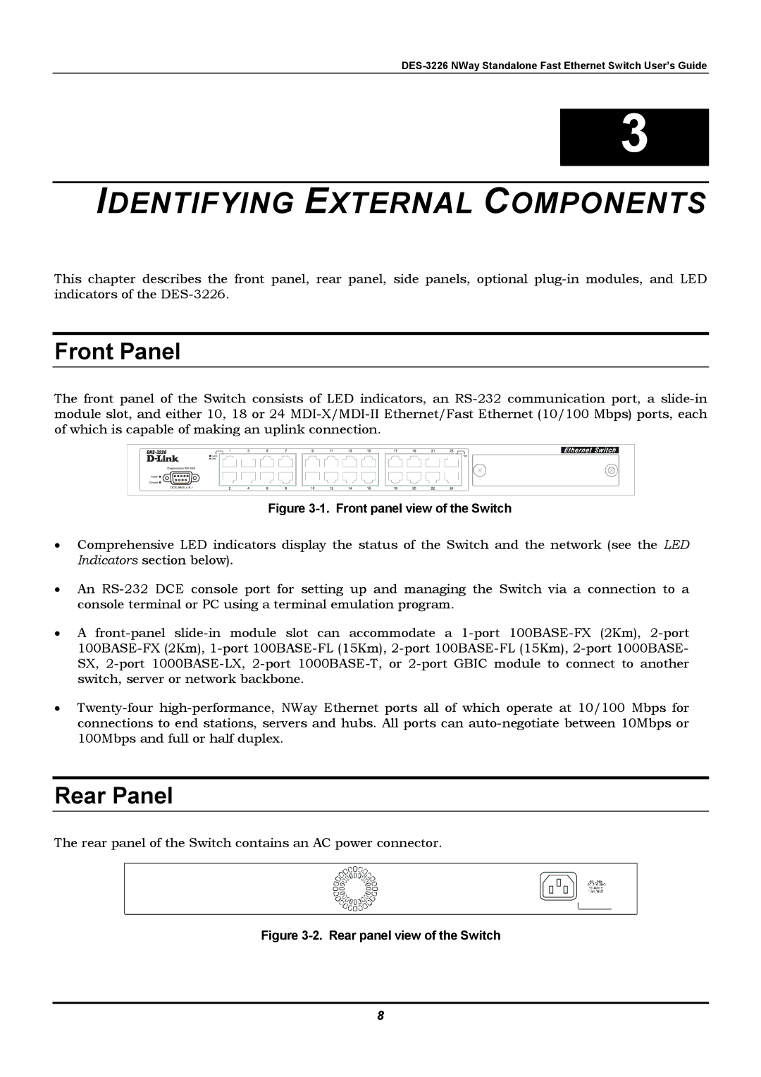
Rear Panel
The rear panel of the Switch contains an AC power connector.
Figure 3-2. Rear panel view of the Switch
8