6DES3624..02 Printed In Taiwan RECYCLABLE
DES-3624 Series Stackable NWay Ethernet Switch User’s Guide
Second Edition April
Wichtige Sicherheitshinweise
LIMITATION OF LIABILITY
WARRANTIES EXCLUSIVE
D-Link Offices for Registration and Warranty Service
Limited Warranty
Hardware
Software
FCC Warning
Copyright Statement
CE Mark Warning
VCCI Warning BSMI Warning
UNPACKING AND SETUP
TABLE OF CONTENTS
CONNECTING THE SWITCH
SWITCH MANAGEMENT CONCEPTS
USING THE CONSOLE INTERFACE
RJ-45 PIN SPECIFICATION
TECHNICAL SPECIFICATIONS
SAMPLE CONFIGURATION FILE
WEB-BASED NETWORK MANAGEMENT
INDEX
RUNTIME SOFTWARE DEFAULT SETTINGS
Conventions
ABOUT THIS GUIDE
Overview of this User’s Guide
Fast Ethernet Technology
INTRODUCTION
Gigabit Ethernet Technology
Features
Switching Technology
Ports
Management
Performance features
Setup
UNPACKING AND SETUP
Desktop or Shelf Installation
Unpacking
Figure 2-1. Switch installed on a Desktop or Shelf
Rack Installation
Figure 2-2A. Attaching the mounting brackets to the Switch
Figure 2-2B. Installing the Switch in an equipment rack
Power Failure
Power On
IDENTIFYING EXTERNAL COMPONENTS
Figure 3-1. Front panel view of the Switches
Front Panel
Rear Panel
Figure 3-2. Rear panel view of the Switches
Side Panels
Figure 3-4. Switch stack with one master and three slaves
Figure 3-3. Side panel views of the Switch
Stack Operation
Optional Plug-in Modules
Figure 3-5. Switch stack with example of possible connections
Stackable NWay Ethernet Switch User’s Guide
Identifying External Components
100BASE-FX SC Module
100BASE-FX MT-RJ Module
Figure 3-6. Two-port, 100BASE-FX MT-RJ module
Figure 3-7. One-port, 100BASE-FX SC module
1000BASE-SX Gigabit Module
100BASE-TX Module
Figure 3-8. Two-port, 100BASE-TX module
Figure 3-9. One-port, 1000BASE-SX gigabit module
1000BASE-T Copper Gigabit Module
1000BASE-LX Gigabit Module
Figure 3-10. One-port, 1000BASE-LX gigabit module
Figure 3-11. One-port, 1000BASE-T gigabit module
Figure 3-12. The Switch LED indicators
LED Indicators
100M These indicators are illuminated green when a 100 Mbps device is connected to any of the 22+2 or 20+2 ports or uplink port. If a 10 Mbps device is connected to any of the 24 ports or uplink port, these LEDs remain dark. When a port is active, these indicators will blink green
Switch to End Node
CONNECTING THE SWITCH
Switch to Hub or Switch
Figure 4-1. Switch connected to an End Node
100BASE-TX Device
10BASE-T Device
Diagnostic Console Port RS-232 DCE
SWITCH MANAGEMENT CONCEPTS
Local Console Management
Traps
IP Addresses and SNMP Community Names
Packet Forwarding
MIBs
Aging Time
Filtering Database
Spanning Tree Algorithm
User-Changeable STA Parameters
STA Operation Levels
On the Bridge Level
On the Port Level
Figure 5-1. Before Applying the STA Rules
Illustration of STA
Figure 5-2. After Applying the STA Rules
Port Trunking
Table 5-1. User-selective STA parameters
Figure 5-3. Port trunking example
VLAN
IEEE 802.1Q VLANs
Figure 5-4. Example of typical VLAN configuration
VLAN Segmentation
Sharing Resources Across VLANs
Port
VLANs Spanning Multiple Switches
PVID
Ports
Figure 5-5. Data transmissions between 802.1Q-compliant Switches
VLANs Over 802.1Q-compliant Switches
Broadcast Management
Port-based Broadcast Packet Filter
Broadcast Storms
MAC-based Broadcast Packet Filter
Setting Up A Console
USING THE CONSOLE INTERFACE
Console Usage Conventions
Connecting to the Switch Using Telnet
Figure 6-1. Example of a console connection
First Time Connecting To The Switch
Figure 6-2. Initial Screen, first time connecting to the Switch
Figure 6-3. Main Menu
User Accounts Management
Administrator and Normal User Privileges
Save Changes
Table 6-1. Administrator and Normal User Privileges
Create/Modify User Accounts
Login On The Switch Console By Registered Users
Figure 6-4. Save Changes screen
Stackable NWay Ethernet Switch User’s Guide
Figure 6-5. User Accounts Management menu
Using the Console Interface
2. Choose Create/Modify User Accounts. The following screen appears
Figure 6-6. Add/Modify User Accounts screen
View/Delete User Accounts
System Configuration
Setting Up The Switch
Figure 6-7. View/Delete User Accounts screen
Figure 6-8. System Configuration menu
Configure IP Address
Figure 6-9. IP Address Configuration screen
Settings on Restart
Configure Console
Figure 6-10. Console Options screen
Figure 6-11. Switch Stack Configuration screen
Configure Switch Stack
Figure 6-12A. Information of Individual Switch Unit screen
Information of Individual Switch Unit
Figure 6-12B. Information of Individual Switch Unit screen
Advance Settings
Figure 6-13. Configure Advanced Switch Features screen
Configure Port
Figure 6-14. Port Configuration screen
Configure Trunk
Figure 6-15. Port Trunk screen
Configure Spanning Tree Protocol
Configure Port Mirroring
Figure 6-16. Port Mirroring Configuration screen
Figure 6-17. Configure Spanning Tree Protocol menu
STP Parameter Settings
Figure 6-18. STP Parameter Setting screen
STP Custom Settings
Figure 6-19. STP Custom Settings screen
Configure Filtering and Forwarding Table
Figure 6-20. Configure Filtering and Forwarding table screen
Figure 6-21. Static Forwarding Table Configuration screen
Configure Static Forwarding Table Entry
Figure 6-22. Custom Filtering Table screen
Configure MAC Address Filtering
Configure IGMP
Configure Permanent Multicast Filtering
Figure 6-23. Static Multicast Filtering Table Configuration screen
Figure 6-24. IGMP Configuration screen
Stackable NWay Ethernet Switch User’s Guide
Figure 6-25. IEEE 802.1q IGMP Configuration screen
Using the Console Interface
Figure 6-26. Add/Remove IGMP Entry screen
Figure 6-27. IEEE 802.1Q IGMP Configuration screen
Configure VLANs & MAC-based Broadcast Domains
Figure 6-28. VLANs & MAC-based Broadcast Domains Configuration screen
Configure MAC-Based Broadcast Domains
Figure 6-29. MAC-Based Broadcast Domains Configuration menu
Figure 6-30. Add/Remove MAC-based Broadcast Domains screen
Stackable NWay Ethernet Switch User’s Guide
Figure 6-31. Add/Remove MAC-based Broadcast Domain Members screen
Using the Console Interface
Figure 6-32. Add/Remove MAC-based Broadcast Domain Members screen
Configure IEEE 802.1Q VLANs
Figure 6-33. IEEE 802.1Q VLANs Configuration menu
Figure 6-34. Ingress Filtering Check screen
Figure 6-35. Default port VLAN assignment screen
Figure 6-36. 802.1Q Static VLAN Settings screen
Figure 6-37. Browse 802.1Q VLAN Entries screen
Update Firmware and Configuration Files
Figure 6-38. Update Firmware and Configuration Files screen
System Utilities
Special Note Concerning Firmware Updates
Figure 6-39. Utilities menu
Ping Test
Save Settings to TFTP Server
Figure 6-40. Ping Test screen
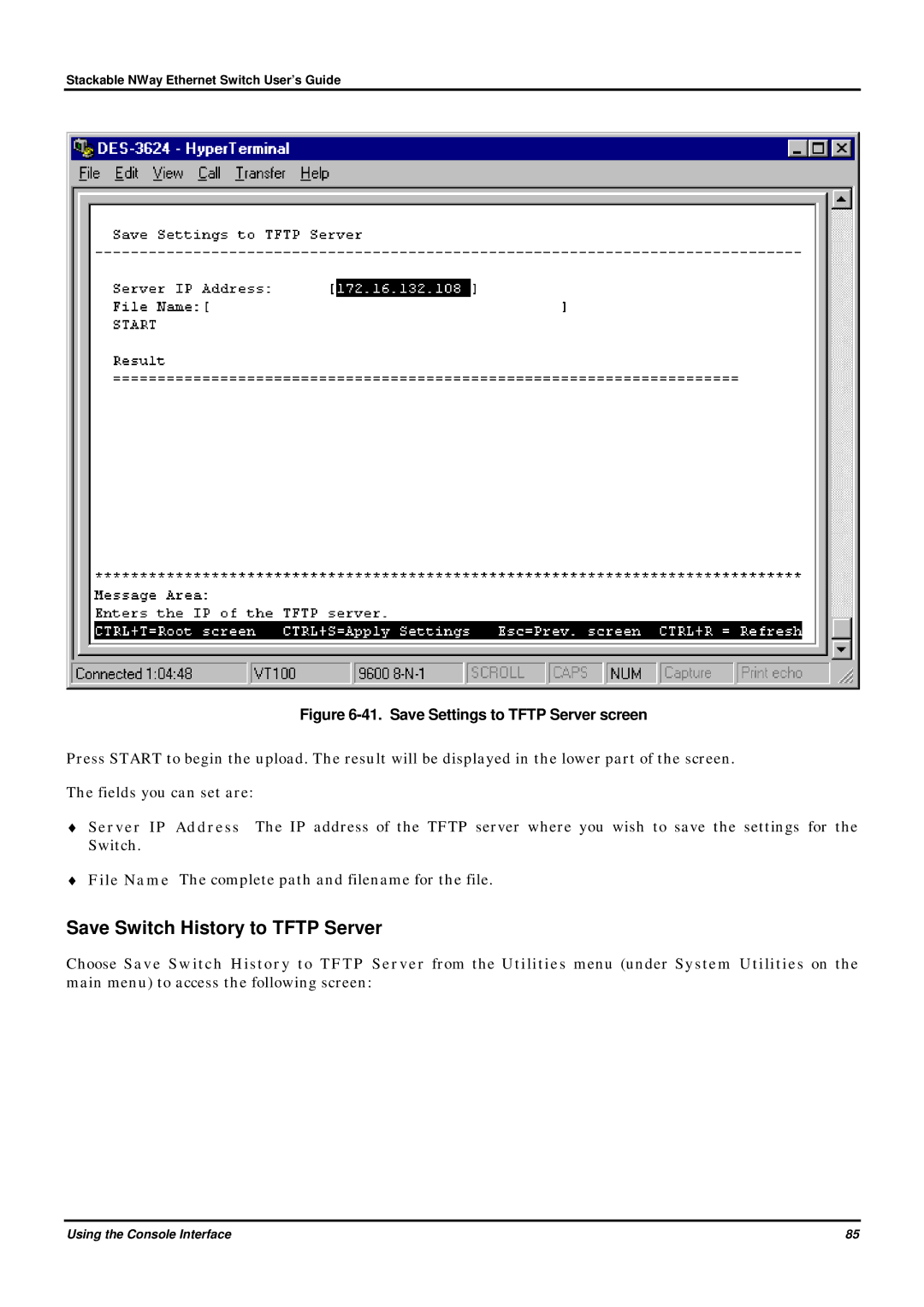
Figure 6-41. Save Settings to TFTP Server screen
Save Switch History to TFTP Server
Community Strings and Trap Stations
Figure 6-42. Save Switch History to TFTP Server screen
Clear Address Table
Figure 6-43. SNMP Manager Configuration screen
Network Monitoring
Switch Monitoring
Figure 6-44. Network Monitoring menu
Port Utilization
Traffic Statistics
Figure 6-45. Traffic Statistics menu
Figure 6-46. Port Utilization screen
Port Traffic Statistics
Figure 6-47. Port Traffic Statistics screen
Figure 6-48. Port Packet Error Statistics table
Port Packet Error Statistics
Figure 6-49. Packet Analysis Statistics table
Port Packet Analysis Statistics
Browse Address Table
Figure 6-50. Browse Address Table
Switch History
Browse IGMP Status
Figure 6-51. Switch History screen
Figure 6-52. IP Multicast Information screen
Factory Reset
Resetting the Switch
Restart System
Figure 6-53. Restart System screen
Logout
Figure 6-54. Factory Reset NV-RAM to Default Value screen
Introduction
WEB-BASED NETWORK MANAGEMENT
Getting Started
Management
Figure 7-1. Configure IP Address window
Configuration
IP Address
Figure 7-2. Configure Switch Stack window
Switch
The information in the window above is described as follows
Advanced
Figure 7-3. Configure Switch Stack - Advanced window
Figure 7-4. Information Of Individual Switch Unit window
Switch Unit
Port
Figure 7-5. Configure Port window
Figure 7-6. Port Trunk window
Port Trunk
Figure 7-7. Port Mirroring window
Port Mirroring
Figure 7-8. STP Parameter Setting window
STP Parameters Setting
Spanning Tree Protocol
Figure 7-9. Spanning Tree Custom Setting window
STP Custom Setting
Forwarding and Filtering
Figure 7-10. Configure Forwarding Table And Filtering Table window
Static Forwarding Table
Click New to access the Static Forwarding Table - Edit window
Figure 7-11. Static Forwarding Table window
Figure 7-12. Static Forwarding Table---Edit window
MAC Address Filtering Table
Click New to access the Static MAC Address Filtering - Edit window
Figure 7-13. Static MAC Address Filtering window
Stackable NWay Ethernet Switch User’s Guide
Figure 7-14. Static MAC Address Filtering---Edit window
Figure 7-15. Static Permanent Multicast Filtering window
Permanent Multicast Filtering
Stackable NWay Ethernet Switch User’s Guide
Web-Based Network Management
Figure 7-16. Static Permanent Multicast Filtering--Edit window
IGMP
Figure 7-17. Configure IGMP window
IGMP Settings
Stackable NWay Ethernet Switch User’s Guide
Web-Based Network Management
Figure 7-18. Add/Remove IGMP Table window
802.1Q IGMP
Figure 7-19. Add/Remove IGMP Table-Edit window
VLANs & MAC-based Broadcast Domains
MAC-Based Broadcast Domains
Figure 7-20. Configure VLAN window
Figure 7-21. Add/Remove MAC-based Broadcast Domains window
Stackable NWay Ethernet Switch User’s Guide
Figure 7-22. Add/Remove MAC-based Broadcast Domains --- Edit window
Description The name of the Broadcast Domain to be added
Web-Based Network Management
Figure 7-23. Add/Remove MAC-based Broadcast Domain Member window
Page
IEEE 802.1Q VLANs
Figure 7-25. Default Port VLAN ID window
Stackable NWay Ethernet Switch User’s Guide
Web-Based Network Management
Stackable NWay Ethernet Switch User’s Guide
Figure 7-26. Port Ingress Filtering Check window
Web-Based Network Management
Click the pointer icon to access the second 802.1Q VLAN Entry window
Figure 7-27. 802.1Q Static VLAN Entry window number one
Stackable NWay Ethernet Switch User’s Guide
Web-Based Network Management
Management
Figure 7-28. 802.1Q Static VLAN Entry window number two
Figure 7-29. Community Strings and Trap Stations window
Community Strings and Trap Stations
Figure 7-30. User Accounts window
User Account
Stackable NWay Ethernet Switch User’s Guide
Web-Based Network Management
Figure 7-31. User Account-Edit window
Console
Figure 7-32. Configure Console window
Figure 7-33. Switch Statistics window
Switch Overview
Monitoring
Figure 7-34. Port Utilization window
Port Utilization
Figure 7-35. Port Traffic Statistics window
Port Traffic Statistics
Figure 7-36. Port Error Packet Statistics window
Port Error Packet Statistics
Web-Based Network Management
Stackable NWay Ethernet Switch User’s Guide
Figure 7-37. Port Packet Analysis window
Port Packet Analysis Statistics
Browse Address Table
Figure 7-38. Browse Address Table window
Browse IGMP Status
Figure 7-39. Browse IGMP Status window
Figure 7-40. Switch History window
Maintenance
Switch History
Figure 7-41. Firmware and Configuration Update window
Firmware and Configuration Update
Figure 7-42. Save Settings To TFTP Server window
Save Settings To TFTP Server
Figure 7-43. Save Switch History To TFTP Server window
Save Switch History To TFTP Server
Figure 7-44. Save Changes window
Save Changes
Stackable NWay Ethernet Switch User’s Guide
Web-Based Network Management
Figure 7-45. Factory Reset to Default Value window
Factory Reset
Stackable NWay Ethernet Switch User’s Guide
Web-Based Network Management
Figure 7-46. Restart System window
Restart System
Stackable NWay Ethernet Switch User’s Guide
Web-Based Network Management
General
TECHNICAL SPECIFICATIONS
Stackable NWay Ethernet Switch User’s Guide
Technical Specifications
Stackable NWay Ethernet Switch User’s Guide
Physical and Environmental
Technical Specifications
General
Technical Specifications
Stackable NWay Ethernet Switch User’s Guide
Performance
Figure B-1. The standard RJ-45 receptacle/connector
RJ-45 PIN SPECIFICATION
Table B-1. The standard Category 3 cable, RJ-45 pin assignment
RJ-45 Connector pin assignment
connection
Commands
SAMPLE CONFIGURATION FILE
Notes about the Configuration File
Defaultgateway
# specify IP address Ipaddr = # specify subnet mask Subnetmask =
# Sample Config File Codetype=PROM Imagefile=e\3624\3624prom.tfp
# specify default gateway Defaultgateway =
Stackable NWay Ethernet Switch User’s Guide
RUNTIME SOFTWARE DEFAULT SETTINGS
INDEX
Forward Delay, 34 Forwarding, 57 Front Panel
tagging
untagging
Offices
Product was purchased from
Registration Card
Product Model
Product Serial No