Stackable NWay Ethernet Switch User’s Guide
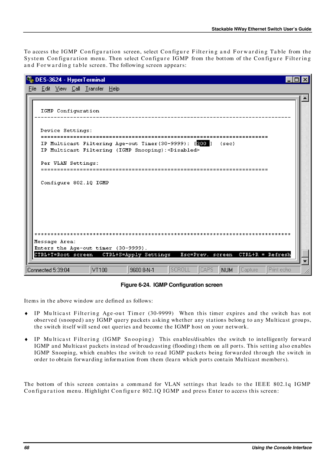
To access the IGMP Configuration screen, select Configure Filtering and Forwarding Table from the System Configuration menu. Then select Configure IGMP from the bottom of the Configure Filtering and Forwarding table screen. The following screen appears:
Figure 6-24. IGMP Configuration screen
Items in the above window are defined as follows:
♦IP Multicast Filtering
♦IP Multicast Filtering (IGMP Snooping) This enables/disables the switch to intelligently forward IGMP and Multicast packets instead of broadcasting (flooding) them on all ports. This setting also enables IGMP Snooping, which enables the switch to read IGMP packets being forwarded through the switch in order to obtain forwarding information from them (learn which ports contain Multicast members).
The bottom of this screen contains a command for VLAN settings that leads to the IEEE 802.1q IGMP Configuration menu. Highlight Configure 802.1Q IGMP and press Enter to access this screen:
68 | Using the Console Interface |