1 | processor fan connector (CPUFAN) | 16 | modem connector (RJ11) |
2 | processor connector (CPU) | 17 | RJ11 internal connector (RJ11INT) |
3 | processor power connector (POWER12V) | 18 | video connector (VGA) |
4 | memory module connectors (2, 4) | 19 | Media Card Reader connector (USBINT) |
5 | memory module connectors (1, 3) | 20 | USB connectors (4) (USB_BACK) |
6 | battery socket (BATTERY) | 21 | network connector (NIC) and USB connectors (2) |
|
|
| (NIC_USB1) |
7 | internal speaker (SPKR) | 22 | |
8 | hard disk fan connector (HDDFAN) | 23 | IEEE 1394 connector (INT1394) |
9 | hard disk connector (SATA0) | 24 | PCI Express x1 connector (SLOT2) |
10 | CD/DVD connector (SATA1) | 25 | PCI Express x16 connector (SLOT1) |
11 | 26 | standby LED (STBYLED) | |
12 | modem | 27 | password jumper (CLRPSWD) |
13 | power connector (POWER) | 28 | RTC reset jumper (CLRCMOS) |
14 | 29 | temperature connector (THRM) | |
| LFE connectors (AUDIOBACK1) |
|
|
15 | S/PDIF audio connector (SPDIF) | 30 | floppy drive connector (FLOPPY) |
Memory
You can increase your computer memory by installing memory modules on the system board.
Your computer supports unbuffered,
NOTE: Buffered memory is not supported on this computer.
DDR2 Memory Overview
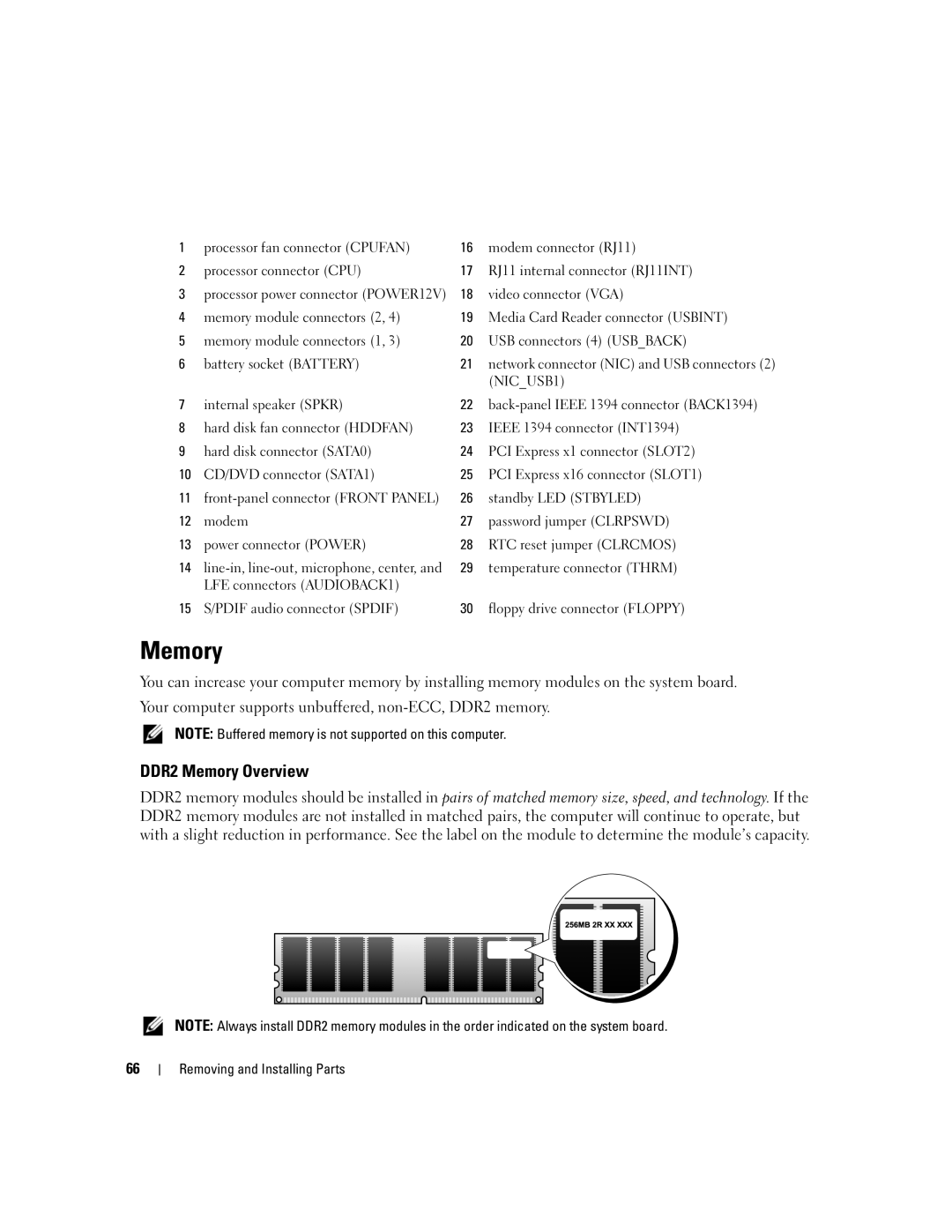
DDR2 memory modules should be installed in pairs of matched memory size, speed, and technology. If the DDR2 memory modules are not installed in matched pairs, the computer will continue to operate, but with a slight reduction in performance. See the label on the module to determine the module’s capacity.
NOTE: Always install DDR2 memory modules in the order indicated on the system board.
66
