Connecting Drive Cables
When you install a drive, you connect two
Drive Interface Connectors
Most interface connectors are keyed for correct insertion; that is, a notch or a missing pin on one connector matches a tab or a
NOTICE: When you connect a SATA interface cable, do not place the colored stripe away from pin 1 of the connector. Reversing the cable prevents the drive from operating and could damage the controller, the drive, or both.
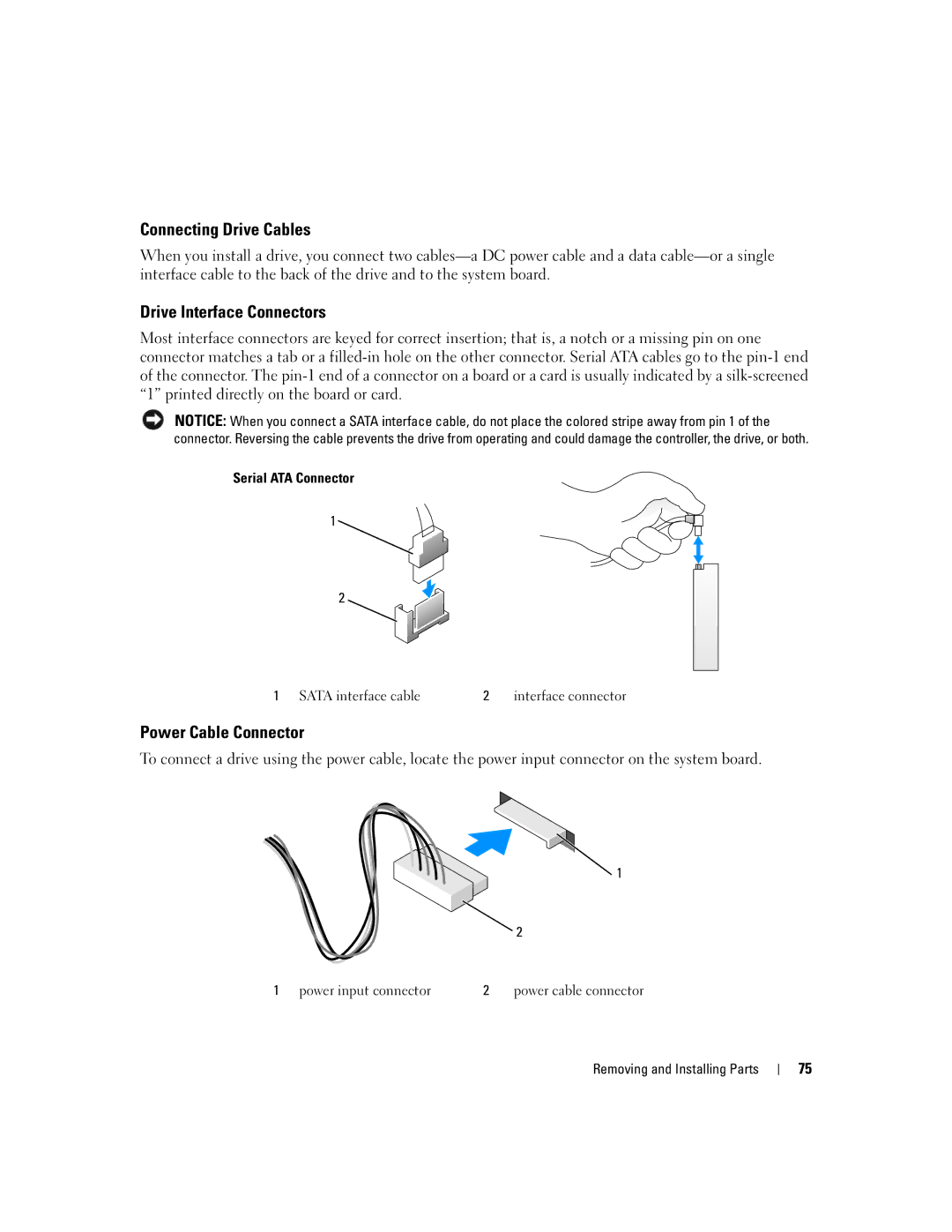
Serial ATA Connector
1![]()
![]()
2
1 SATA interface cable | 2 interface connector |
Power Cable Connector
To connect a drive using the power cable, locate the power input connector on the system board.
1
2
1 power input connector | 2 | power cable connector |
Removing and Installing Parts
75