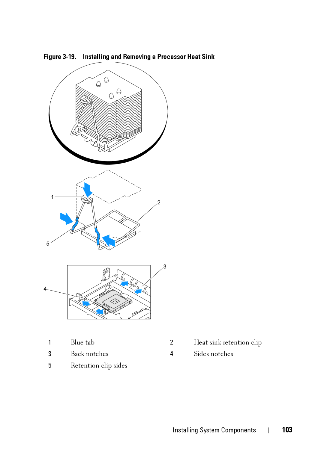
Figure 3-19. Installing and Removing a Processor Heat Sink
1
2
5 ![]()
3 |
4 |
1 | Blue tab | 2 | Heat sink retention clip |
3 | Back notches | 4 | Sides notches |
5Retention clip sides
Installing System Components
1
2
5 ![]()
3 |
4 |
1 | Blue tab | 2 | Heat sink retention clip |
3 | Back notches | 4 | Sides notches |
5Retention clip sides
Installing System Components