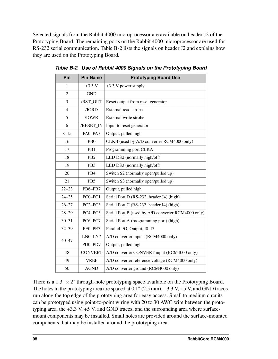
Selected signals from the Rabbit 4000 microprocessor are available on header J2 of the Prototyping Board. The remaining ports on the Rabbit 4000 microprocessor are used for
Table
Pin | Pin Name | Prototyping Board Use | |
1 | +3.3 V | +3.3 V power supply | |
|
|
| |
2 | GND |
| |
|
|
| |
3 | /RST_OUT | Reset output from reset generator | |
|
|
| |
4 | /IORD | External read strobe | |
|
|
| |
5 | /IOWR | External write strobe | |
|
|
| |
6 | /RESET_IN | Input to reset generator | |
|
|
| |
Output, pulled high | |||
|
|
| |
16 | PB0 | CLKB (used by A/D converter RCM4000 only) | |
|
|
| |
17 | PB1 | Programming port CLKA | |
|
|
| |
18 | PB2 | LED DS2 (normally high/off) | |
|
|
| |
19 | PB3 | LED DS3 (normally high/off) | |
|
|
| |
20 | PB4 | Switch S2 (normally open/pulled up) | |
|
|
| |
21 | PB5 | Switch S3 (normally open/pulled up) | |
|
|
| |
Output, pulled high | |||
|
|
| |
Serial Port D | |||
|
|
| |
Serial Port C | |||
|
|
| |
Serial Port B (used by A/D converter RCM4000 only) | |||
|
|
| |
Serial Port A (programming port) (high) | |||
|
|
| |
Parallel I/O, Output, | |||
|
|
| |
A/D converter inputs (RCM4000 only) | |||
|
| ||
Output, pulled high | |||
| |||
|
|
| |
48 | CONVERT | A/D converter CONVERT input (RCM4000 only) | |
|
|
| |
49 | VREF | A/D converter reference voltage (RCM4000 only) | |
|
|
| |
50 | AGND | A/D converter ground (RCM4000 only) | |
|
|
|
There is a 1.3" × 2"
98 | RabbitCore RCM4000 |