2.2.2 Attach Module to Prototyping Board
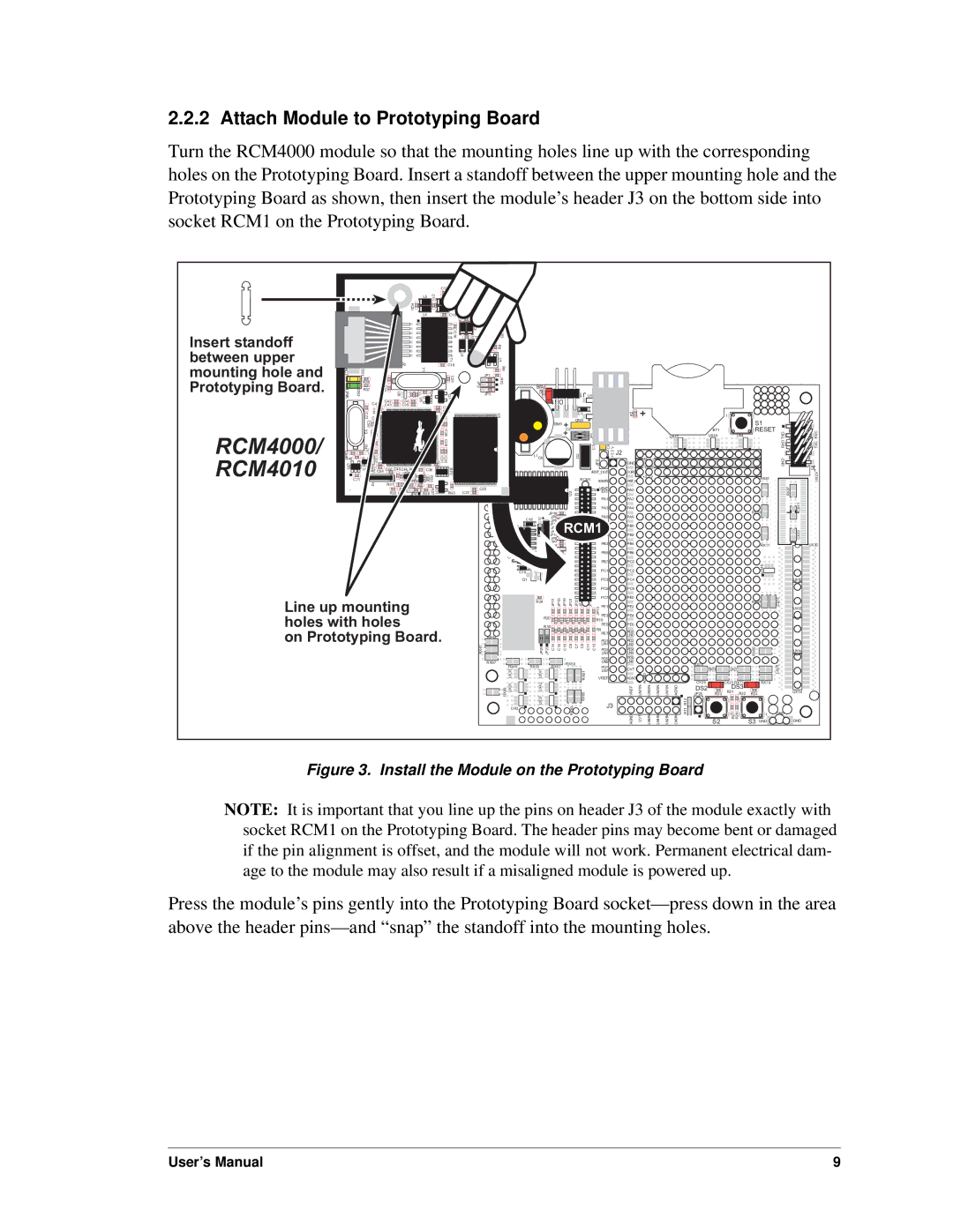
Turn the RCM4000 module so that the mounting holes line up with the corresponding holes on the Prototyping Board. Insert a standoff between the upper mounting hole and the Prototyping Board as shown, then insert the module’s header J3 on the bottom side into socket RCM1 on the Prototyping Board.
|
|
|
|
|
|
|
|
|
|
|
|
| C12 |
|
| R34 |
|
|
|
|
|
|
|
|
|
|
|
|
|
|
|
|
|
|
|
|
|
|
|
|
|
|
|
|
|
| J1 |
|
|
|
|
|
|
|
|
|
|
| |
|
|
|
|
|
|
|
|
|
|
| L5 | C11 | C14 |
| C8 |
|
|
|
|
|
|
|
|
|
|
|
|
| |
|
|
|
|
|
|
|
|
| R20 |
|
| L6 |
|
|
| R1 |
|
|
|
|
|
|
|
|
|
| |||
|
|
|
|
|
|
|
|
|
|
| L7 | C9 | C7 |
|
|
|
|
|
|
|
|
|
|
| |||||
|
|
|
|
|
|
|
|
|
|
| L4 |
| C15 | L3 | R7 |
|
|
|
|
|
|
|
|
|
|
|
|
| |
|
|
|
|
|
|
|
|
|
|
|
|
|
| R6 |
|
| R2 |
|
|
|
|
|
|
|
|
|
| ||
|
|
|
|
|
|
|
|
|
|
|
|
|
|
|
|
|
|
|
|
|
|
|
|
|
|
| |||
|
|
|
|
|
|
|
|
|
|
|
|
|
|
|
| L2 |
|
| R4 |
|
|
|
|
|
|
|
|
|
|
Insert standoff |
|
|
|
|
|
|
|
|
|
|
|
| C16 |
| C13 |
| R5 | R3 |
|
|
|
|
|
|
|
|
|
| |
|
|
|
|
|
|
|
|
|
|
|
|
|
|
|
| C10 | R51 | R8 |
|
|
|
|
|
|
|
|
|
| |
between upper |
|
|
|
|
|
|
|
|
|
|
|
|
|
| L8 | L9 |
|
|
|
|
|
|
|
|
|
|
| ||
|
|
|
|
|
|
|
|
|
|
|
|
|
|
|
|
|
|
|
|
|
|
|
|
|
|
| |||
|
|
|
|
|
|
| J2 |
|
|
|
| C18T1 |
|
|
|
|
| U1 |
|
|
|
|
|
|
|
|
|
| |
mounting hole and | ACT |
| DS1 |
|
|
| C41 R35 |
|
|
| Y1 |
| C20 |
|
|
| JP1 | R9 |
|
|
|
|
|
|
|
|
|
| |
Prototyping Board. |
| R36 |
|
|
|
|
|
|
|
|
| JP2 |
|
| R10 |
|
|
|
|
|
|
|
|
|
| ||||
| R37 |
|
|
|
|
| C33 |
|
|
|
|
|
|
| PWR |
|
|
|
|
|
| ||||||||
|
|
|
|
|
|
|
|
|
| JP3 |
|
|
|
|
| J1 | U1 |
|
|
| |||||||||
| LINK | DS2 |
|
|
| U7 | C42 | U6C34 | R25 | U5 | R24 | Q1 |
|
|
|
|
|
|
|
|
| R1 | DS1 |
|
|
| |||
|
| C47 |
|
|
|
|
|
|
|
|
|
|
|
|
|
| |||||||||||||
|
|
|
|
| C43 | C35 |
|
|
|
| C24 |
|
|
|
|
|
|
|
|
|
|
|
|
|
|
| |||
|
|
| C72 | C49C48 |
|
|
|
|
|
|
| C25 |
|
|
|
|
|
|
|
|
|
|
| C1 |
|
|
| R2 | |
|
|
|
|
|
|
|
|
|
| C26 C27 |
|
|
|
|
| U3 |
|
|
|
|
|
|
|
| |||||
|
|
|
|
|
|
|
|
|
|
|
|
|
|
|
|
|
|
|
| GND |
|
|
| ||||||
|
|
| C50 |
|
|
|
|
|
|
|
|
|
|
|
|
|
|
|
|
|
|
| GND |
|
|
|
| ||
|
|
|
|
|
|
|
|
|
|
|
|
|
|
|
|
|
|
|
|
|
| C2 |
|
|
|
| |||
|
|
| Y3 | C51 |
|
|
|
|
|
|
|
| C28 C29 |
|
|
|
|
|
|
|
|
|
|
|
|
|
|
| |
RCM4000/ |
|
|
|
|
|
|
|
|
|
|
|
|
|
|
|
|
|
|
|
|
|
| JP1 |
|
|
| |||
C66 |
| R47 | C52 |
|
|
|
|
|
|
|
|
|
|
|
|
| C5 |
|
|
|
|
|
| C3 |
| C4 V | J2 | ||
| C54 |
|
|
|
|
|
|
|
|
|
|
|
|
|
|
|
| L1 | C6 |
|
|
| |||||||
RCM4010 | R46 |
|
|
| C53 |
|
|
|
|
|
| C32 | C30 C31 |
|
|
|
|
|
|
|
|
|
| D2 |
| JP2 | +3.3 |
| |
U17 |
| U18R48 |
|
|
|
|
|
|
|
|
|
|
|
|
|
|
|
|
|
| GND | ||||||||
|
| C46 C45C44 R29 |
| C36 |
|
|
|
|
|
|
|
|
|
|
|
| /IORD | ||||||||||||
|
| C55C56 |
| U9 |
|
| U8 |
| RP2 |
|
|
|
|
|
|
|
|
|
|
|
| /RST_OUT | |||||||
C71 |
| Y2 |
|
|
| R30 |
| R26 |
|
|
|
|
|
|
|
|
|
|
| RCM1 | /IOWR | /RST_IN | |||||||
|
|
|
|
| R31 |
|
|
|
|
|
|
|
|
|
|
|
|
|
|
|
|
|
| ||||||
|
|
|
|
|
|
|
|
|
| C38 | D1 R27 |
|
|
| C22 |
|
|
|
|
|
|
|
|
| VBAT | PA0 | |||
|
|
|
|
|
|
| R33 R32 | JP4 |
| R28 | R43 |
| C23 |
|
|
|
|
|
|
|
|
| U2 |
|
| EXT | |||
|
|
|
|
|
|
|
|
|
|
|
|
|
|
|
|
|
|
|
|
|
|
|
|
|
|
|
| PA1 | PA2 |
|
|
|
|
|
|
|
|
|
|
|
|
|
|
|
|
|
|
|
|
|
|
|
|
|
|
|
| PA3 | PA4 |
|
|
|
|
|
|
|
|
|
|
|
|
|
|
|
|
|
|
|
|
|
|
| JP16 |
|
|
|
|
| |
|
|
|
|
|
|
|
|
|
|
|
|
|
|
|
|
|
|
|
|
| C18 | C17 | JP6 |
|
|
| PA5 | PA6 | |
|
|
|
|
|
|
|
|
|
|
|
|
|
|
|
|
|
|
| C20 |
| JP5 |
|
|
|
|
| |||
|
|
|
|
|
|
|
|
|
|
|
|
|
|
|
|
|
|
| U3 |
| JP12 |
|
|
| PA7 | PB0 | |||
|
|
|
|
|
|
|
|
|
|
|
|
|
|
|
|
|
|
|
|
|
|
|
| JP4 | RCM1PB1 |
| |||
|
|
|
|
|
|
|
|
|
|
|
|
|
|
|
|
|
|
|
|
|
|
|
| JP3 |
| ||||
|
|
|
|
|
|
|
|
|
|
|
|
|
|
|
|
|
|
|
|
|
|
|
| JP14 | PB2 | ||||
|
|
|
|
|
|
|
|
|
|
|
|
|
|
|
|
|
|
|
|
|
|
| C16 | JP8 |
|
|
|
|
|
|
|
|
|
|
|
|
|
|
|
|
|
|
|
|
|
|
|
|
|
|
|
| JP7 |
|
|
| PB3 | PB4 | |
|
|
|
|
|
|
|
|
|
|
|
|
|
|
|
|
|
|
|
|
|
|
| JP18 |
|
|
| |||
|
|
|
|
|
|
|
|
|
|
|
|
|
|
|
|
|
|
|
|
|
|
|
| JP9 |
|
|
|
|
|
|
|
|
|
|
|
|
|
|
|
|
|
|
|
|
|
|
|
| C19 |
|
|
| JP10 |
|
|
| PB5 | PB6 | |
|
|
|
|
|
|
|
|
|
|
|
|
|
|
|
|
|
|
|
|
|
|
|
|
|
|
|
|
| |
|
|
|
|
|
|
|
|
|
|
|
|
|
|
|
|
|
|
|
|
|
|
|
|
|
|
|
| PB7 | PC0 |
+5 V
GND +3.3 V
|
| 1 |
|
| S1 |
| BT1 | RESET |
UX47 | UX49 | UX4 |
RX81
RX83 ![]()
RX11
TXD | RXC |
RXD | TXC |
GND | J4 |
| UX29 |
| RX87 |
CX41 |
CX39 |
UX30
|
| R25 |
|
|
|
|
|
|
|
|
|
|
| C15 | R26 |
|
|
|
|
|
|
|
| PC1 | PC2 |
| Q1 |
|
|
|
|
|
|
|
| PC3 | PC4 | |
|
|
|
|
|
|
|
|
|
| |||
|
|
|
|
|
|
|
|
|
|
| PC5 | PC6 |
Line up mounting |
| R29 | JP11 JP15 | JP19 | JP21 JP22 JP20 | JP17 |
| PC7 | PE0 | |||
|
|
|
| |||||||||
|
| JP13 | PE1 | PE2 | ||||||||
|
|
|
| |||||||||
holes with holes |
| R20 | R18 | R16 | R14 | R13 | R15 | R17 |
| PE3 | PE4 | |
| R19 |
| ||||||||||
|
|
| PE5 | PE6 | ||||||||
| R10 |
|
|
|
|
|
|
|
| |||
on Prototyping Board. |
|
| R8 | R6 | R4 | R3 | R5 | R7 | R9 | PE7 | PD0 | |
|
|
| ||||||||||
RX43 |
|
|
|
|
|
|
|
|
| LN0 | ||
|
|
|
|
|
|
|
|
|
| PD1 | PD2 | |
RX47 | JP24 JP23 | C14 C12 | C10 | C8 C7 C9 C11 C13 |
| LN1 | LN2 | |||||
|
| PD3 | PD4 | |||||||||
|
| LN3 | LN4 | |||||||||
|
|
|
|
|
|
|
|
|
|
| PD5 | PD6 |
| RX97 | RX55 | RX57 |
| RX59 |
|
|
| LN5 | LN6 | ||
| RX49 |
|
|
|
|
|
| PD7 | CVT | |||
| UX33 | UX41 |
|
|
|
|
| RX61 |
| LN7 | ||
|
|
|
|
|
| VREF | AGND | |||||
| RX89 UX31 | UX37 UX42 |
|
|
|
|
| RX65 |
| J3 | VREF | |
| UX3 |
|
|
|
|
| RX63 |
|
|
|
| |
|
|
|
|
|
|
|
|
|
|
| AGND | |
| AGND |
|
LN7IN | LN5IN | LN3IN |
CVT | LN6IN | LN4IN |
UX45 |
|
|
|
| UX10 |
RX67 | CX17 |
|
|
| UX12 |
RX85 |
| UX14 |
|
| RX75 |
|
|
|
| CX29 |
|
|
| RX73 | CX27 |
|
| |
|
| CX25 |
| CX23 RX77 |
| RX79 | |
LN1IN | AGND | DS2 |
| DS3 |
|
| |
JP25 | R23 | R21 | R22 | R24 | UX16 | ||
LN2IN | LN0IN | R12 | S2 | R27 R28 | S3 |
|
|
R11 | GND | GND | |||||
|
|
|
| 1 |
| 1 | GND |
Figure 3. Install the Module on the Prototyping Board
NOTE: It is important that you line up the pins on header J3 of the module exactly with socket RCM1 on the Prototyping Board. The header pins may become bent or damaged if the pin alignment is offset, and the module will not work. Permanent electrical dam- age to the module may also result if a misaligned module is powered up.
Press the module’s pins gently into the Prototyping Board
User’s Manual | 9 |