Many other possible ranges are possible by physically changing the resistor values that make up the attenuator circuit.
NOTE: Analog input LN7_IN does not have the 10 kΩ resistor installed, and so no resistor attenuator is available, limiting its maximum input voltage to 2 V. This input is intended to be used for a thermistor that you may install at header location JP25.
It is also possible to read a negative voltage on
Differential measurements require two channels. As the name differential implies, the dif- ference in voltage between the two adjacent channels is measured rather than the differ- ence between the input and analog ground. Voltage measurements taken in differential mode have a resolution of 12 bits, with the 12th bit indicating whether the difference is positive or negative.
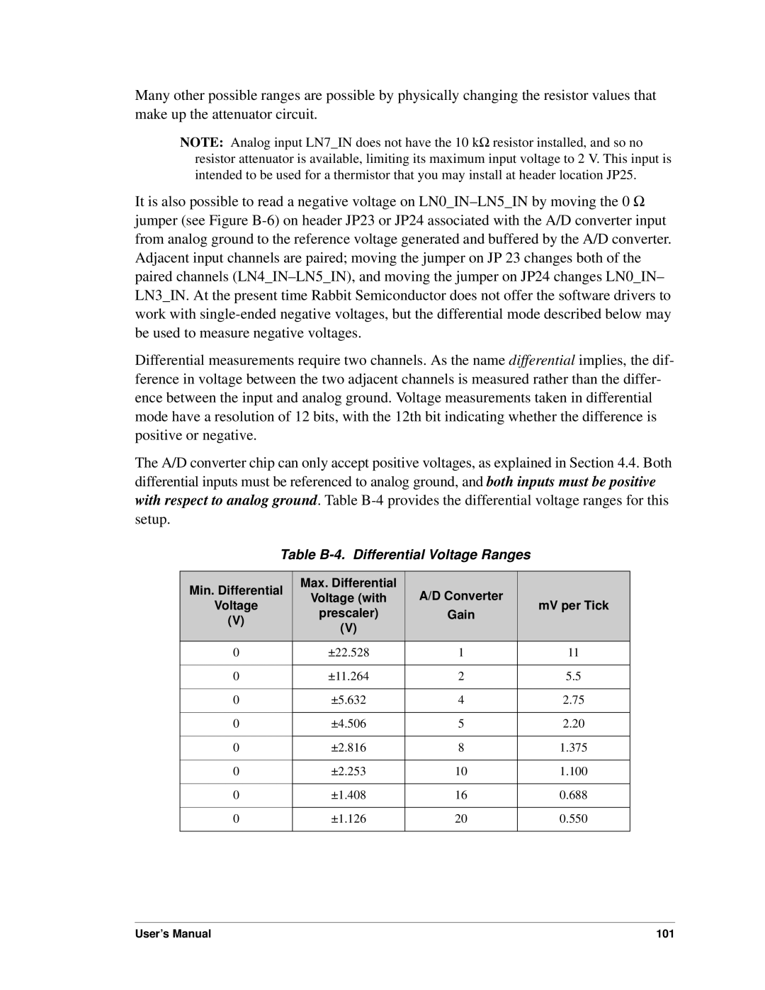
The A/D converter chip can only accept positive voltages, as explained in Section 4.4. Both differential inputs must be referenced to analog ground, and both inputs must be positive with respect to analog ground. Table
Table B-4. Differential Voltage Ranges
Min. Differential
Voltage
(V)
Max. Differential
Voltage (with
prescaler)
(V)
A/D Converter
Gain
mV per Tick
0 | ±22.528 | 1 | 11 |
|
|
|
|
0 | ±11.264 | 2 | 5.5 |
|
|
|
|
0 | ±5.632 | 4 | 2.75 |
|
|
|
|
0 | ±4.506 | 5 | 2.20 |
|
|
|
|
0 | ±2.816 | 8 | 1.375 |
|
|
|
|
0 | ±2.253 | 10 | 1.100 |
|
|
|
|
0 | ±1.408 | 16 | 0.688 |
|
|
|
|
0 | ±1.126 | 20 | 0.550 |
|
|
|
|
User’s Manual | 101 |