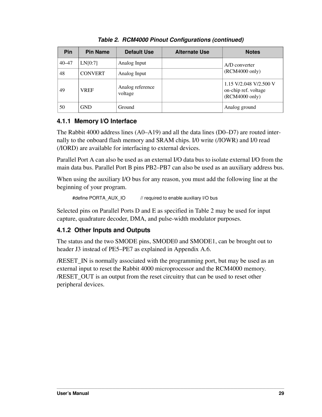
Table 2. RCM4000 Pinout Configurations (continued)
Pin | Pin Name | Default Use | Alternate Use | Notes |
|
|
|
|
|
LN[0:7] | Analog Input |
| A/D converter | |
|
|
|
| |
|
|
|
| (RCM4000 only) |
48 | CONVERT | Analog Input |
| |
|
| |||
|
|
|
|
|
|
| Analog reference |
| 1.15 V/2.048 V/2.500 V |
49 | VREF |
| ||
voltage |
| |||
|
|
| (RCM4000 only) | |
|
|
|
| |
|
|
|
|
|
50 | GND | Ground |
| Analog ground |
|
|
|
|
|
4.1.1 Memory I/O Interface
The Rabbit 4000 address lines
Parallel Port A can also be used as an external I/O data bus to isolate external I/O from the main data bus. Parallel Port B pins
When using the auxiliary I/O bus for any reason, you must add the following line at the beginning of your program.
#define PORTA_AUX_IO // required to enable auxiliary I/O bus
Selected pins on Parallel Ports D and E as specified in Table 2 may be used for input capture, quadrature decoder, DMA, and
4.1.2 Other Inputs and Outputs
The status and the two SMODE pins, SMODE0 and SMODE1, can be brought out to header J3 instead of
/RESET_IN is normally associated with the programming port, but may be used as an external input to reset the Rabbit 4000 microprocessor and the RCM4000 memory. /RESET_OUT is an output from the reset circuitry that can be used to reset other peripheral devices.
User’s Manual | 29 |