B.4.1 Adding Other Components

There are pads for 28-pin TSSOP devices, 16-pin SOIC devices, and 6-pin SOT devices that can be used for surface-mount prototyping with these devices. There are also pads that can be used for SMT resistors and capacitors in an 0805 SMT package. Each component has every one of its pin pads connected to a hole in which a 30 AWG wire can be soldered (standard wire wrap wire can be soldered in for point-to-point wiring on the Prototyping Board). Because the traces are very thin, carefully determine which set of holes is con- nected to which surface-mount pad.

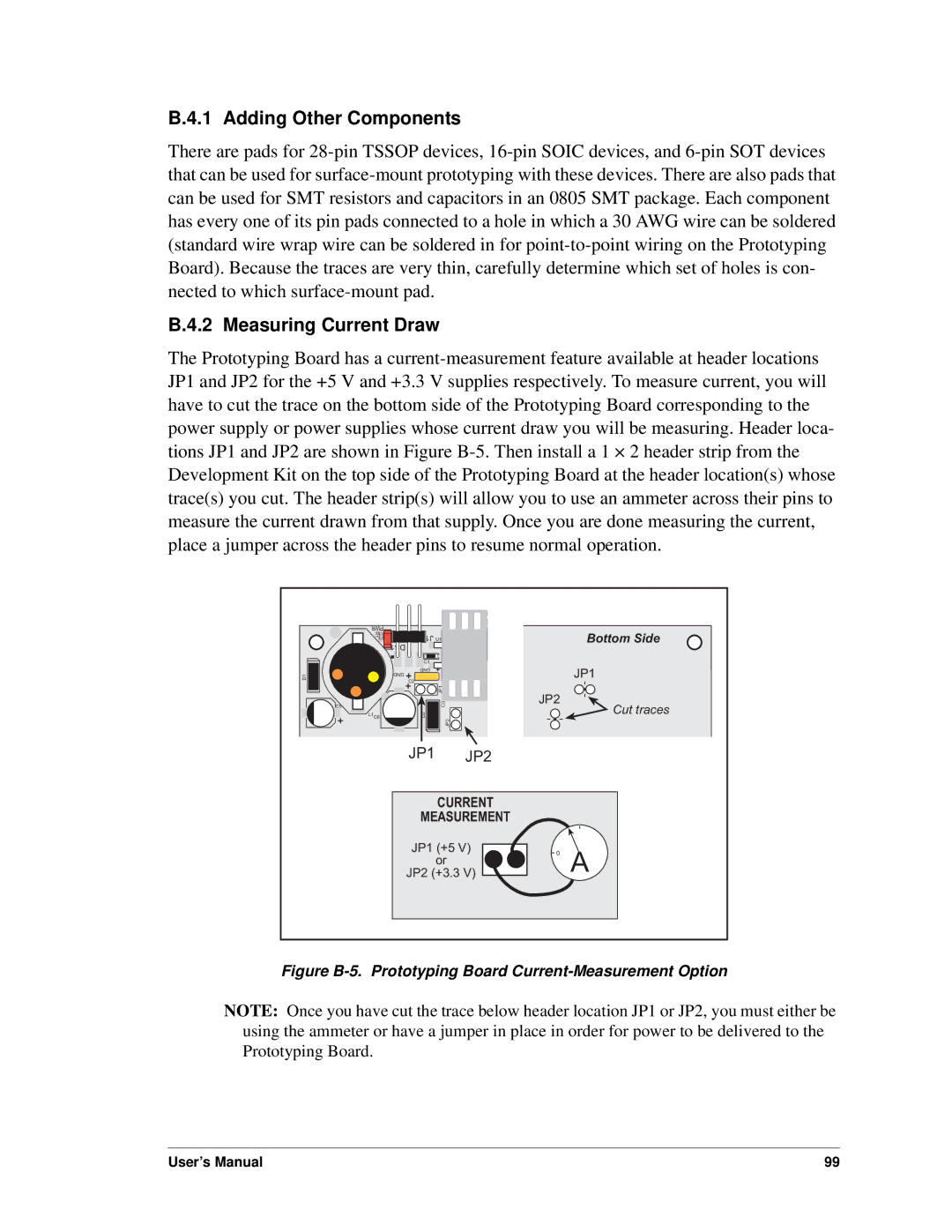
B.4.2 Measuring Current Draw

The Prototyping Board has a current-measurement feature available at header locations JP1 and JP2 for the +5 V and +3.3 V supplies respectively. To measure current, you will have to cut the trace on the bottom side of the Prototyping Board corresponding to the power supply or power supplies whose current draw you will be measuring. Header loca- tions JP1 and JP2 are shown in Figure B-5.Then install a 1 × 2 header strip from the Development Kit on the top side of the Prototyping Board at the header location(s) whose trace(s) you cut. The header strip(s) will allow you to use an ammeter across their pins to measure the current drawn from that supply. Once you are done measuring the current, place a jumper across the header pins to resume normal operation.

D1

PWR


R1

J1

U1


DS1


C1


GND


GND


C2


JP1

C5


C3


L1C6

D2

JP2


JP1

JP2

Bottom Side

JP1

JP2

Cut traces

CURRENT

MEASUREMENT

JP1 (+5 V)

0

A

or


JP2 (+3.3 V)


Figure B-5. Prototyping Board Current-Measurement Option

NOTE: Once you have cut the trace below header location JP1 or JP2, you must either be using the ammeter or have a jumper in place in order for power to be delivered to the Prototyping Board.

User’s Manual

99

Page 105
Image 105
Digi RCM4000 user manual Adding Other Components, Measuring Current Draw