B.4.4 Serial Communication
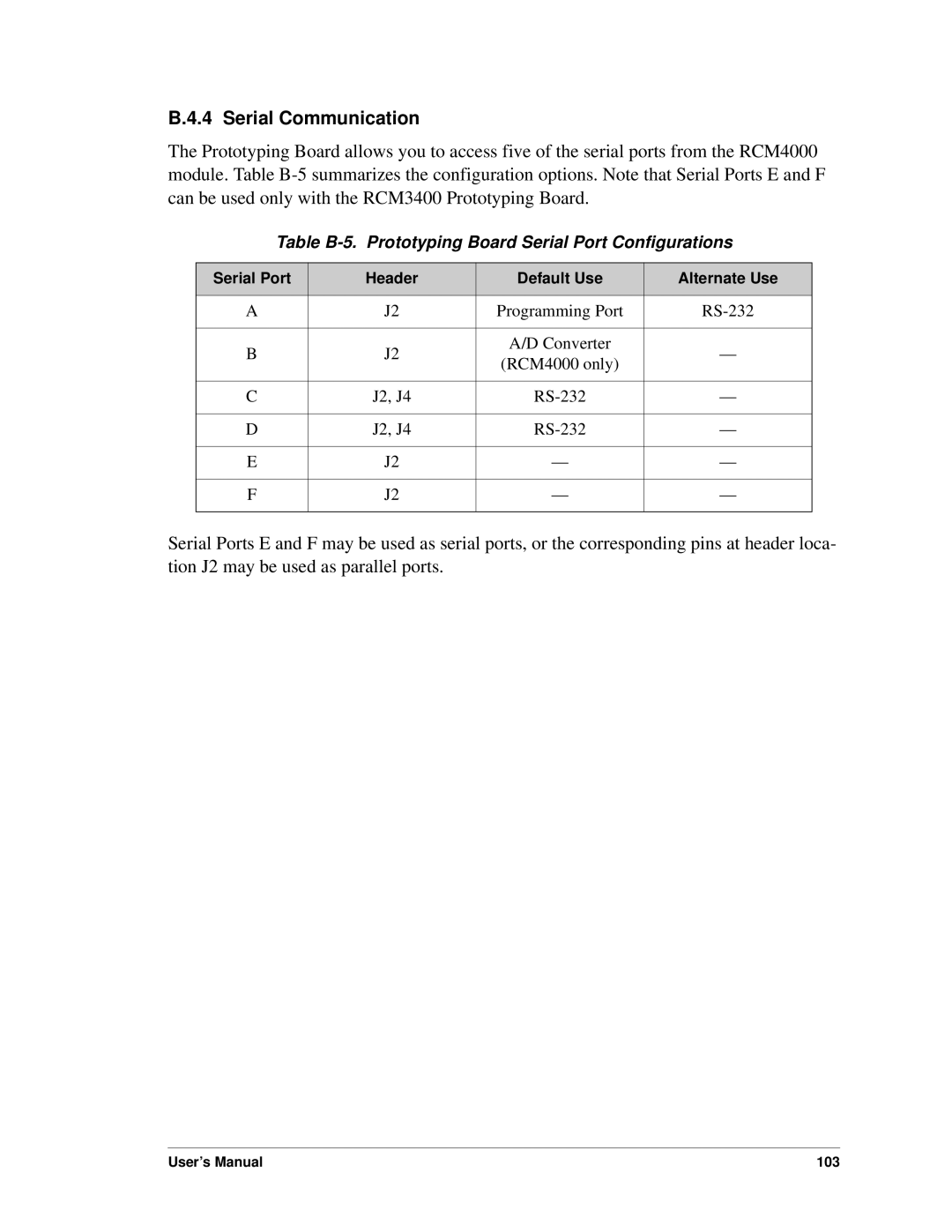
The Prototyping Board allows you to access five of the serial ports from the RCM4000 module. Table
Table B-5. Prototyping Board Serial Port Configurations
Serial Port | Header | Default Use | Alternate Use | |
|
|
|
| |
A | J2 | Programming Port | ||
|
|
|
| |
B | J2 | A/D Converter | — | |
(RCM4000 only) | ||||
|
|
| ||
|
|
|
| |
C | J2, J4 | — | ||
|
|
|
| |
D | J2, J4 | — | ||
|
|
|
| |
E | J2 | — | — | |
|
|
|
| |
F | J2 | — | — | |
|
|
|
|
Serial Ports E and F may be used as serial ports, or the corresponding pins at header loca- tion J2 may be used as parallel ports.
User’s Manual | 103 |