•
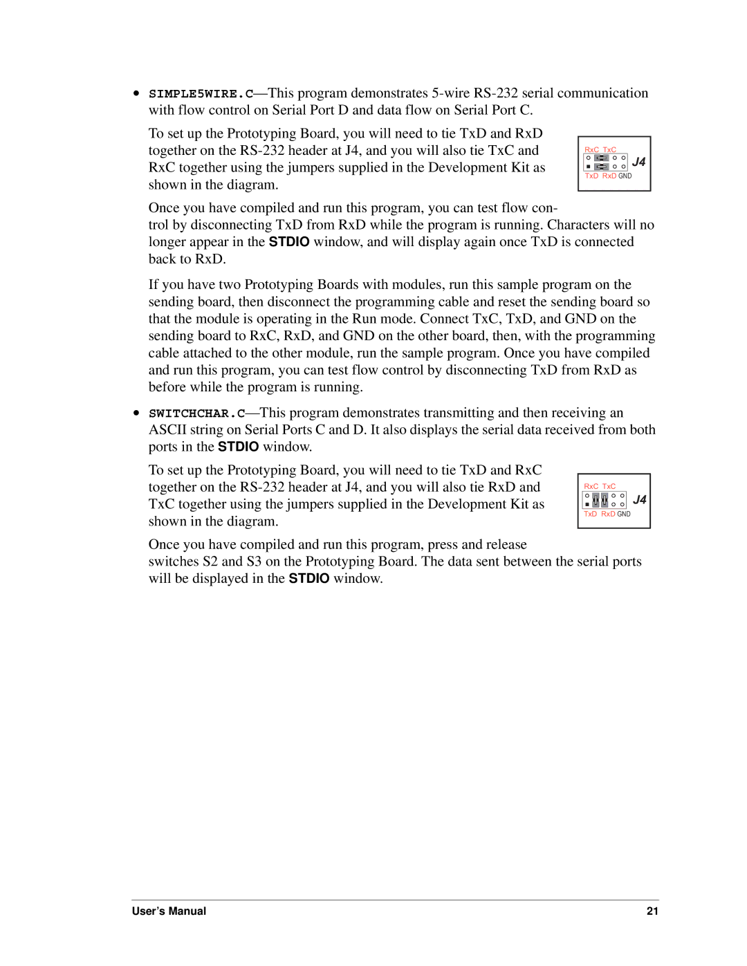
To set up the Prototyping Board, you will need to tie TxD and RxD together on the
RxC TxC
![]() J4
J4
TxD RxD GND
Once you have compiled and run this program, you can test flow con-
trol by disconnecting TxD from RxD while the program is running. Characters will no longer appear in the STDIO window, and will display again once TxD is connected back to RxD.
If you have two Prototyping Boards with modules, run this sample program on the sending board, then disconnect the programming cable and reset the sending board so that the module is operating in the Run mode. Connect TxC, TxD, and GND on the sending board to RxC, RxD, and GND on the other board, then, with the programming cable attached to the other module, run the sample program. Once you have compiled and run this program, you can test flow control by disconnecting TxD from RxD as before while the program is running.
•
To set up the Prototyping Board, you will need to tie TxD and RxC together on the
RxC TxC
J4
TxD RxD GND
Once you have compiled and run this program, press and release
switches S2 and S3 on the Prototyping Board. The data sent between the serial ports will be displayed in the STDIO window.
User’s Manual | 21 |