+3.3 V_IN ![]()
![]() /RESET_OUT
/RESET_OUT ![]()
![]() /IOWR
/IOWR ![]()
![]()
VBAT_EXT ![]()
![]() PA1
PA1 ![]()
![]() PA3
PA3 ![]()
![]() PA5
PA5 ![]()
![]() PA7
PA7 ![]()
![]() PB1
PB1 ![]()
![]() PB3
PB3 ![]()
![]() PB5
PB5 ![]()
![]() PB7
PB7 ![]()
![]() PC1
PC1 ![]()
![]() PC3
PC3 ![]()
![]() PC5
PC5 ![]()
![]() PC7
PC7 ![]()
![]() PE1
PE1 ![]()
![]() PE3
PE3 ![]()
![]()
PE5/SMODE0 ![]()
![]()
![]() PE7/STATUS
PE7/STATUS ![]()
![]()
![]() LN1
LN1 ![]()
![]()
![]() LN3
LN3 ![]()
![]()
![]() LN5
LN5 ![]()
![]()
![]() LN7
LN7 ![]()
![]()
![]()
n.c./VREF ![]()
![]()
![]()
![]()
![]() GND
GND
![]()
![]()
![]() /IORD
/IORD
![]()
![]()
![]() /RESET_IN
/RESET_IN
![]()
![]()
![]() PA0
PA0
![]()
![]()
![]() PA2
PA2
![]()
![]()
![]() PA4
PA4
![]()
![]()
![]() PA6
PA6
![]()
![]()
![]() PB0
PB0
![]()
![]()
![]() PB2
PB2
![]()
![]()
![]() PB4
PB4
![]()
![]()
![]() PB6
PB6
![]()
![]()
![]() PC0
PC0
![]()
![]()
![]() PC2
PC2
![]()
![]()
![]() PC4
PC4
![]()
![]()
![]() PC6
PC6
![]()
![]()
![]() PE0
PE0
![]()
![]()
![]() PE2
PE2
![]()
![]()
![]() PE4
PE4
![]()
![]()
![]() PE6/SMODE1
PE6/SMODE1
![]()
![]()
![]() LN0
LN0
![]()
![]()
![]() LN2
LN2
![]()
![]()
![]() LN4
LN4
![]()
![]()
![]() LN6
LN6
![]()
![]()
![]() CONVERT
CONVERT
![]()
![]()
![]() GND
GND
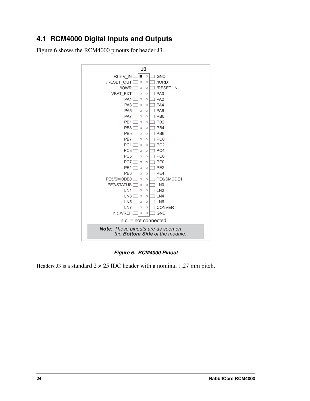
n.c. = not connected
Note: These pinouts are as seen on the Bottom Side of the module.
Figure 6. RCM4000 Pinout
Headers J3 is a standard 2 × 25 IDC header with a nominal 1.27 mm pitch.
24 | RabbitCore RCM4000 |