int anaInCalib(int channel, int opmode, int gaincode, int value1, float volts1, int value2, float volts2);
Calibrates the response of the desired A/D converter channel as a linear function using the two conver- sion points provided. Four values are calculated and placed into global tables _adcCalibS, _adcCalibD, and adcCalibM to be later stored into simulated EEPROM using the function anaInEEWr(). Each channel will have a linear constant and a voltage offset.
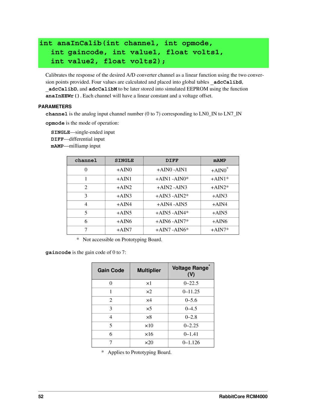
PARAMETERS
channel is the analog input channel number (0 to 7) corresponding to LN0_IN to LN7_IN opmode is the mode of operation:
channel | SINGLE | DIFF | mAMP |
|
|
|
|
0 | +AIN0 | +AIN0 | +AIN0* |
1 | +AIN1 | +AIN1 | +AIN1* |
|
|
|
|
2 | +AIN2 | +AIN2 | +AIN2* |
|
|
|
|
3 | +AIN3 | +AIN3 | +AIN3 |
|
|
|
|
4 | +AIN4 | +AIN4 | +AIN4 |
|
|
|
|
5 | +AIN5 | +AIN5 | +AIN5 |
|
|
|
|
6 | +AIN6 | +AIN6 | +AIN6 |
|
|
|
|
7 | +AIN7 | +AIN7 | +AIN7* |
|
|
|
|
* Not accessible on Prototyping Board.
gaincode is the gain code of 0 to 7:
Gain Code | Multiplier | Voltage Range* | |
(V) | |||
|
| ||
0 | ×1 | ||
|
|
| |
1 | ×2 | ||
|
|
| |
2 | ×4 | ||
|
|
| |
3 | ×5 | ||
|
|
| |
4 | ×8 | ||
|
|
| |
5 | ×10 | ||
|
|
| |
6 | ×16 | ||
|
|
| |
7 | ×20 |
| |
|
|
|
* Applies to Prototyping Board.
52 | RabbitCore RCM4000 |