4.2.2 Ethernet Port
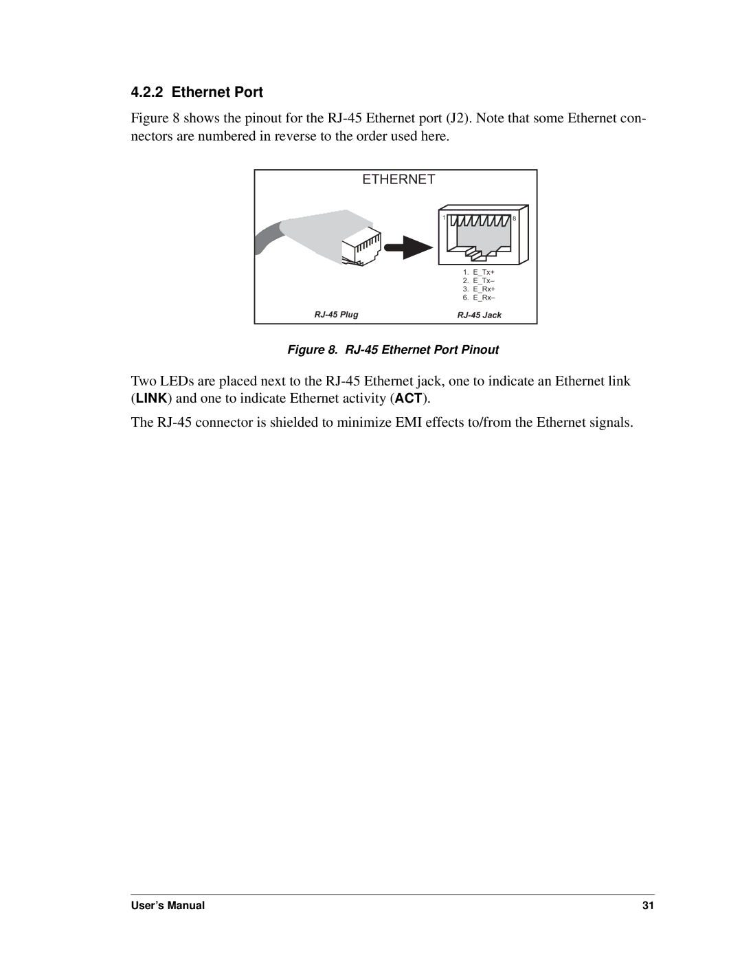
Figure 8 shows the pinout for the RJ-45 Ethernet port (J2). Note that some Ethernet con- nectors are numbered in reverse to the order used here.
| ETHERNET |
|
| 1 | 8 |
| 1. | E_Tx+ |
| 2. | E_Tx– |
| 3. | E_Rx+ |
| 6. | E_Rx– |
Figure 8. RJ-45 Ethernet Port Pinout
Two LEDs are placed next to the
The
User’s Manual | 31 |