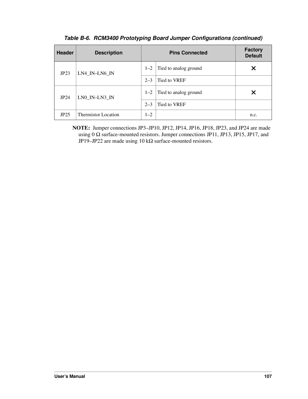
Table B-6. RCM3400 Prototyping Board Jumper Configurations (continued)
Header | Description |
| Pins Connected | Factory |
| Default | |||
|
|
|
| |
|
|
|
|
|
JP23 |
| Tied to analog ground | × | |
|
|
| ||
|
| Tied to VREF |
| |
|
|
|
|
|
JP24 |
| Tied to analog ground | × | |
|
|
| ||
|
| Tied to VREF |
| |
|
|
|
|
|
JP25 | Thermistor Location |
| n.c. | |
|
|
|
|
|
NOTE: Jumper connections
User’s Manual | 107 |