4.4 A/D Converter (RCM4000 only)
The RCM4000 has an onboard ADS7870 A/D converter whose scaling and filtering are done via the motherboard on which the RCM4000 module is mounted. The A/D converter multiplexes converted signals from eight
The eight analog input pins,
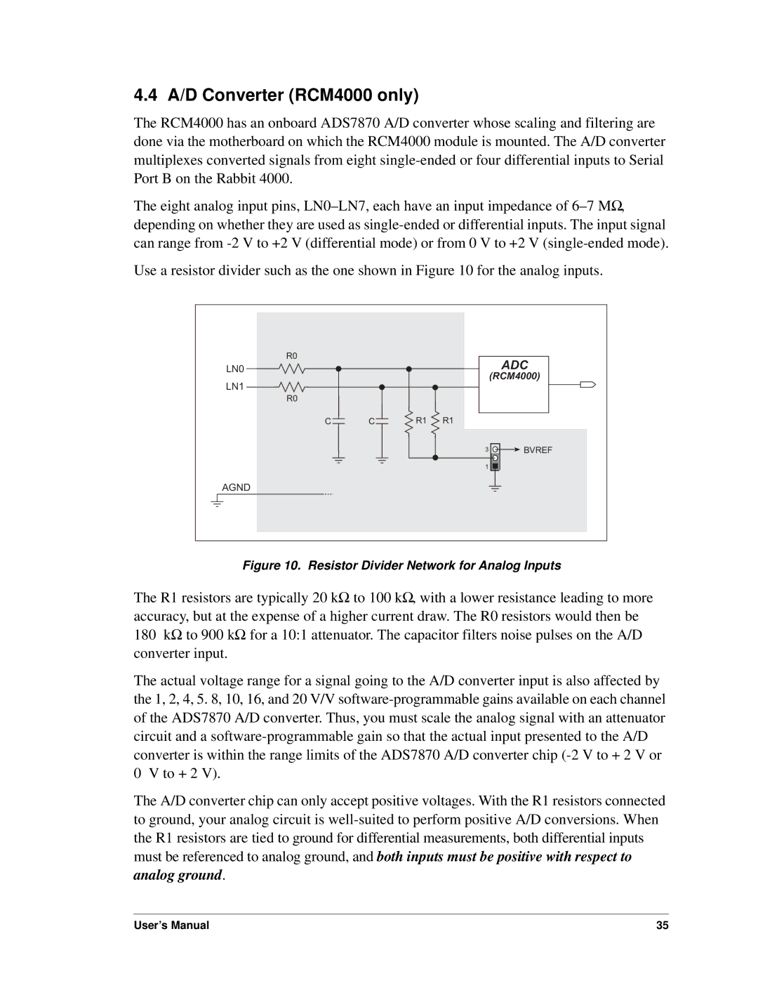
Use a resistor divider such as the one shown in Figure 10 for the analog inputs.
R0 |
|
|
| ADC |
LN0 |
|
|
| |
|
|
|
| (RCM4000) |
LN1 |
|
|
| ADC |
R0 |
|
|
|
|
C | C | R1 | R1 |
|
|
|
| 3 | BVREF |
|
|
| 1 |
|
AGND |
|
|
|
|
Figure 10. Resistor Divider Network for Analog Inputs
The R1 resistors are typically 20 kΩ to 100 kΩ, with a lower resistance leading to more accuracy, but at the expense of a higher current draw. The R0 resistors would then be
180kΩ to 900 kΩ for a 10:1 attenuator. The capacitor filters noise pulses on the A/D converter input.
The actual voltage range for a signal going to the A/D converter input is also affected by the 1, 2, 4, 5. 8, 10, 16, and 20 V/V
The A/D converter chip can only accept positive voltages. With the R1 resistors connected to ground, your analog circuit is
User’s Manual | 35 |
