B.5 Prototyping Board Jumper Configurations
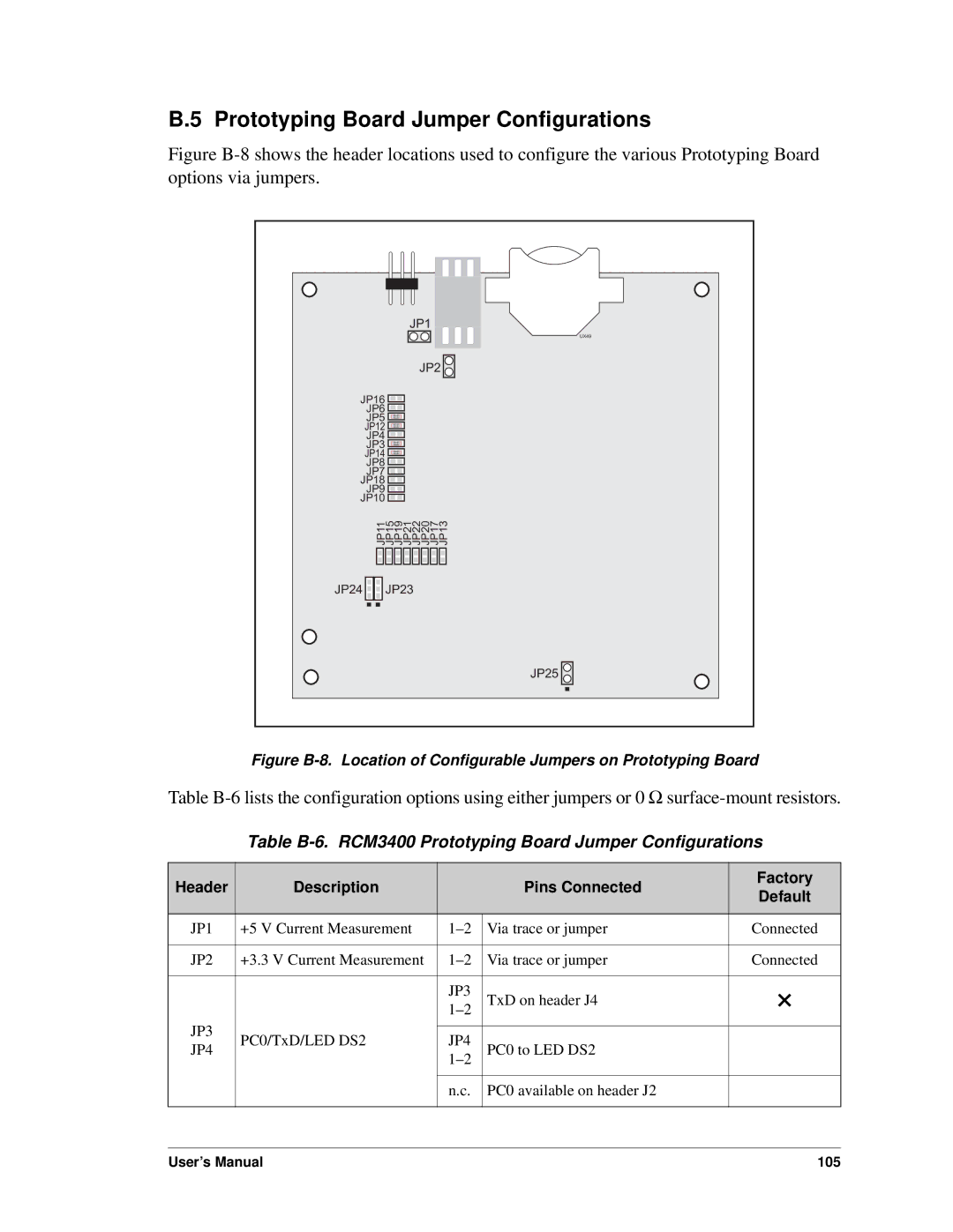
Figure B-8 shows the header locations used to configure the various Prototyping Board options via jumpers.
| JP1 |
| UX49 |
| JP2 |
JP16 |
|
JP6 |
|
JP5 |
|
JP12 |
|
JP4 |
|
JP3 |
|
JP14 |
|
JP8 |
|
JP7 |
|
JP18 |
|
JP9 |
|
JP10 |
|
JP11 JP15 JP19 JP21 JP22 JP20 JP17 JP13 | |
JP24 | JP23 |
| JP25 |
Figure B-8. Location of Configurable Jumpers on Prototyping Board
Table
Table B-6. RCM3400 Prototyping Board Jumper Configurations
Header | Description |
| Pins Connected | Factory |
| Default | |||
|
|
|
| |
|
|
|
|
|
JP1 | +5 V Current Measurement | Via trace or jumper | Connected | |
|
|
|
|
|
JP2 | +3.3 V Current Measurement | Via trace or jumper | Connected | |
|
|
|
|
|
|
| JP3 | TxD on header J4 | × |
|
| |||
JP3 |
|
|
|
|
PC0/TxD/LED DS2 | JP4 |
|
| |
JP4 | PC0 to LED DS2 |
| ||
|
| |||
|
|
|
|
|
|
| n.c. | PC0 available on header J2 |
|
|
|
|
|
|
User’s Manual | 105 |