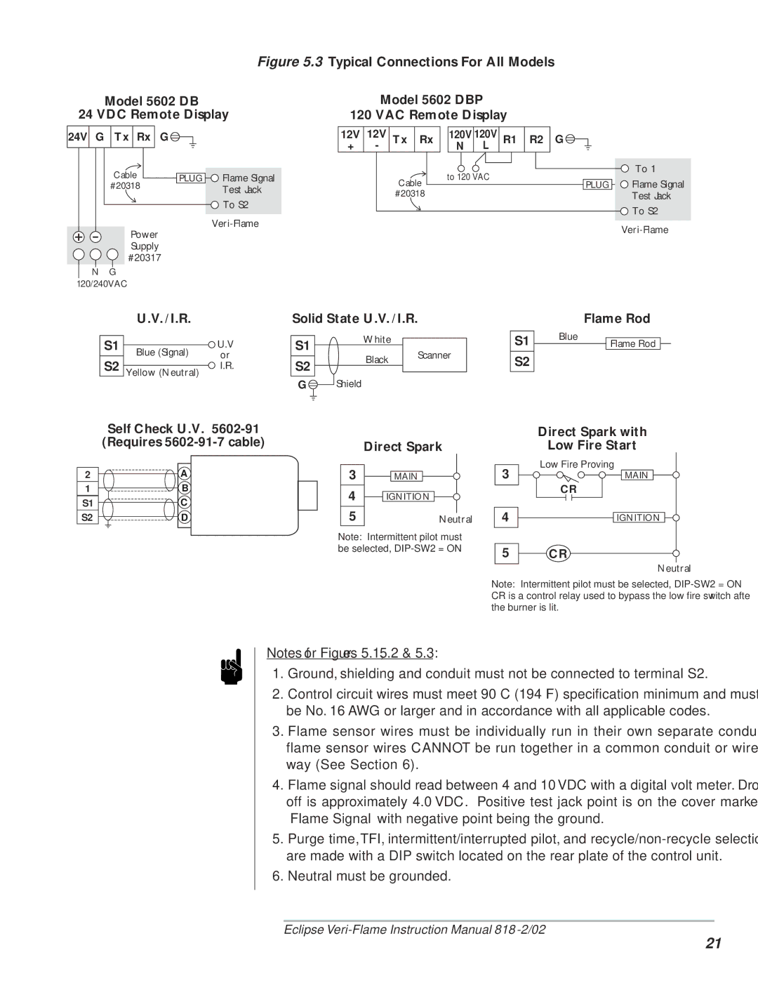
5600, VeriFlame Single Burner Monitoring System specifications
The Eclipse Combustion VeriFlame Single Burner Monitoring System, model 5600, represents a significant advancement in the field of combustion management technology. Designed to provide enhanced monitoring and control of burner operations, the VeriFlame system is equipped with state-of-the-art features that ensure optimal efficiency, safety, and performance in a variety of industrial applications.One of the main features of the VeriFlame 5600 is its advanced flame detection technology, which employs efficient optical sensors to monitor flame presence and stability continuously. This feature enables the system to provide real-time feedback, ensuring that burners operate within specified parameters and respond swiftly to any fluctuations. The system’s intelligent analytics can easily discern between normal operational conditions and potential hazards, enhancing safety and reducing the risk of unsafe operation.
The VeriFlame system is also known for its versatile communication capabilities, featuring multiple connectivity options. The unit can integrate seamlessly with existing plant control systems using industry-standard protocols such as Modbus or Profibus. This interoperability allows for comprehensive data sharing and centralized control of multiple burner systems from a single interface, streamlining operations and improving operator efficiency.
Another notable characteristic of the Eclipse Combustion VeriFlame is its user-friendly interface. The system comes with an intuitive graphical display that provides operators with critical operational data, including flame quality, burner status, and diagnostic information. This straightforward interface facilitates quick decision-making and troubleshooting, minimizing downtime and enhancing the overall operational efficiency of the burner system.
The 5600 model also offers robust diagnostic capabilities, allowing for proactive maintenance and reduced unexpected failures. It features built-in self-check routines and historical data logging, which provide valuable insights into system performance over time. These diagnostic tools empower operators to identify and address potential issues before they escalate, thereby reducing maintenance costs and enhancing the longevity of the burner components.
Moreover, the VeriFlame system is designed with flexibility in mind, accommodating various burner types and fuel sources. This adaptability makes it suitable for use in a wide range of industries, including oil and gas, power generation, and manufacturing.
In conclusion, the Eclipse Combustion VeriFlame Single Burner Monitoring System 5600 stands out due to its advanced flame detection, versatile communication options, user-friendly interface, robust diagnostics, and flexibility. Together, these features make it an essential tool for optimizing combustion processes, enhancing safety, and improving overall operational efficiency in industrial environments.

