Manuals
/
Emerson
/
Computer Equipment
/
Switch
Emerson
Static Transfer Switch
user manual
PS212801
Models:
Static Transfer Switch
1
40
152
152
Download
152 pages
63.42 Kb
37
38
39
40
41
42
43
44
Page 40
Image 40
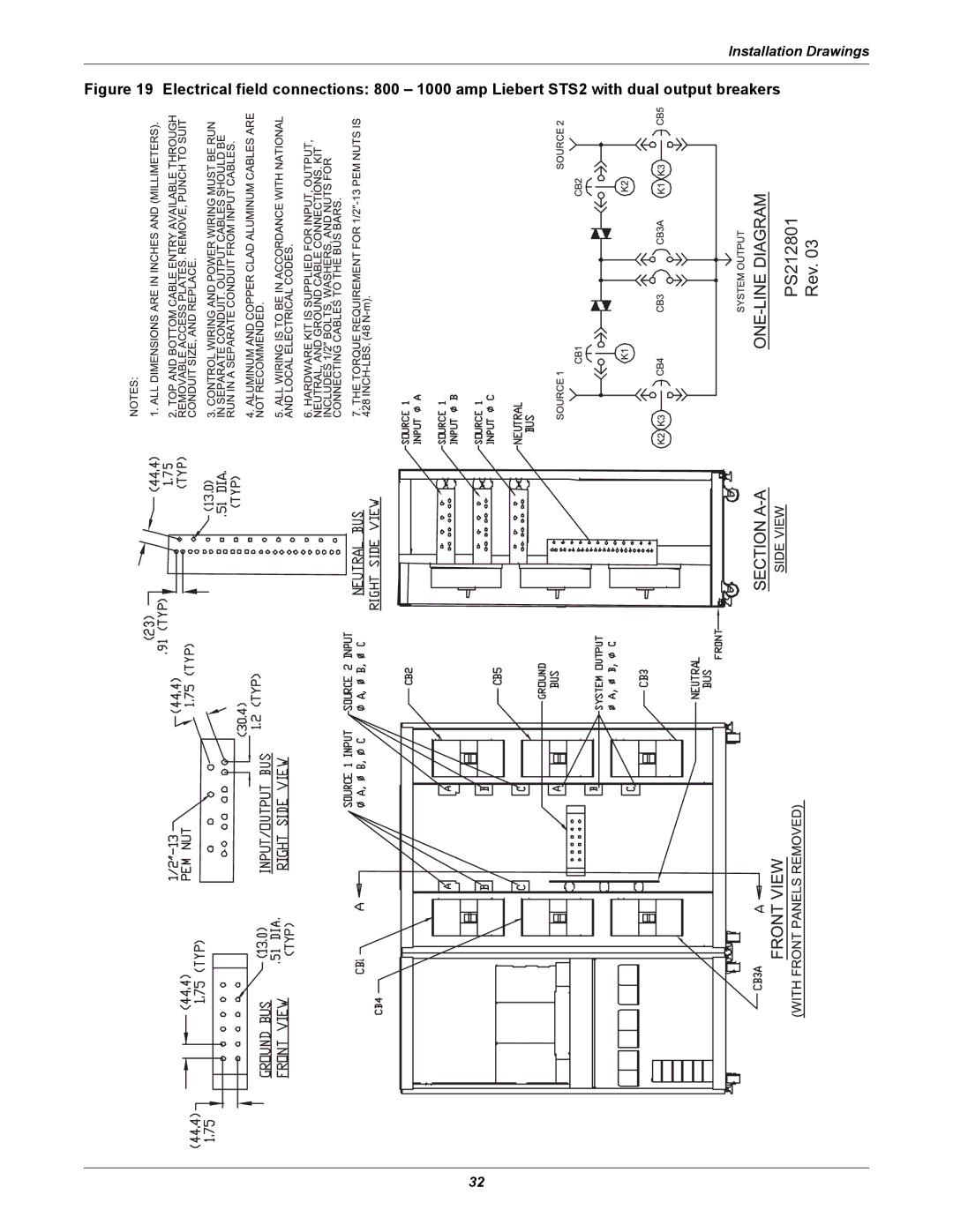
Installation Drawings
Figure 19 Electrical field connections: 800 – 1000 amp Liebert STS2 with dual output breakers
Rev. 03
PS212801
32
Page 39
Page 41
Page 40
Image 40
Page 39
Page 41
Contents
Liebert Static Transfer Switch
Page
Table of Contents
Alarm and Faults
Theory of Operation
Communication Interfaces
Specifications
Liebert STS2 Touch Screen Display
Event Message Help Text Maintenance
System Components
Figures
Tables
Important Safety Instructions
Overview of Manual
Safety Precautions
Unloading and Handling
External Inspections
Unpacking and Inspections
Handling Considerations
Internal Inspections
Unit Preparation
Recommended Minimum Service Clearances
Heat Output
Operating Environment
Location Considerations
Altitude
Recommended derating for high altitude operation
Leveling of the Static Switch Without Anchoring
Leveling and Anchoring the Static Switch Using Floor Stand
Leveling and Anchoring the Unit to the Floor
Locating the Liebert STS2
Input And Output Power Connections
Power and Control Wiring
Input/output conduit plate specifications
Input Junction Box Installation-Optional
Rating Max. number and size
Input junction box dimensions
Input junction box terminal wire size range
Length Width Height Switch Rating Inches mm
Switch Rating Power and Ground Lug Wire Range
Control Wiring Connections
System Grounding
Source MICB1 MICB2 Isolation Transformer
CB1 STS1 STS2 CB2
Remote Source Selection Wiring
Power Supply
Remote source selection terminal block
Contact Connection
Programmable Relay Board
Optimized Transfer
Options
Programmable relay board pinout
Comms Board
Input Contact Isolator Board
Liebert IntelliSlot Web/485 Card With Adapter
Key Lockout Switch
LED Display
Remote Source Selection
Redundant Output Breaker
Seismic Floor Anchors
Input Junction Boxes and Cables
Seismic Floor Stand
Installation Drawings
Outline drawing 100 250 amp Liebert STS2
Rev
Outline drawing 800 1000 amp Liebert STS2
PS211101 Rev
PS211401
PS211801
Seismic anchor
Seismic anchor drawing 400 600 amp Liebert STS2
Front
System Seismic ANCHORING, Figure
Electrical field connections
Drawing 100 250 amp Liebert STS2 with single output breaker
Rev
Drawing 400 600 amp Liebert STS2 with single output breaker
Ground BUS INPUT/OUTPUT BUS Front View Right Side View
PS212401
Breaker
Drawing 800 1000 amp Liebert STS2 with single output
PS212801
Liebert STS2 non-automatic circuit breaker schedule
Control connection location diagram 100 600 amp Liebert STS2
See Option Location Detail
Control Wiring
Front View with Front Door Removed Option Location Detail
See Note
J71
J72
J73
J74
Control wiring for the input contact isolator board option
Table J51
02-810015-XX
TB3 TB3
DB-9J3
Control wiring for the RS-232 port
TXD RXD GND
Input Junction BOX
Mimic
ColorLCD Load touch screendisplay
Symbol
Description
Installation drawing, seismic floor stand 100-250A
Installation
Stand
PS215002 Rev
PS215003 Rev
Hardware Torque Chart
Height Table
PS216001 Rev
PS216002 Rev
PS216003 Rev
Installation drawing, seismic floor stand 800-1000A
800
Drawing
Right Side View
Front Right Isometric View Rear Right Isometric View
Detail a
Side View
Right
Front View
View
Introduction to Liebert STS2 Operations
System Description
Redundancy
Modes of Operation
Operator Controls
Bypass
General Description
Theory of Operation
Detailed Component Description
Hardware
Firmware
Circuit Breakers
SCRs
Logic Modules
Audible Alarm
6 RS-232 Port
Operating Instructions for the Touch Screen Interface
Normal System Turn-On
Settings on
Manual Transfer / Preferred Source Selection
Enabling Remote Source Selection
Maintenance Bypass
To manually select the preferred source
Viewing Slot for the Source 2 Gate Drive Board
Touch Screen Viewing Slot for the Source 1 Gate Drive Board
To bypass the switch for Source
Bypass Procedures for Source
To return to the normal mode
Shutdown in Static Transfer Switch Mode
Shutdown in Maintenance Bypass Mode
To return to normal mode
Normal System Shutdown
Alarm and Faults
Event Mask
Event Log
Event and History Logs
History Log
Alarm Notes
List of Messages
Alarm Message Description/Cause Action
Event messages
See Configuring the Input Contact Isolator Settings on
Using the RS-232 Port
Communication Interfaces
Terminal commands
Connecting and Using a Terminal
Keys Function
Configuring the Liebert STS2 via the Terminal
Groups Parameter
Item Parameter
UPMDR?
Value Parameter
Group settings and values
Value types
User
Event Mask
Options1
Setting Bitpacked Options with the Terminal
Comms Options
Critical Option Enabling
Non-Critical Option Enabling
Binary-hexadecimal conversions
Hex
Putting the Terminal Command Together
Setting Event Masks with the Terminal
Examples of Event Mask Settings
Display Overview
Liebert STS2 Touch Screen Display
Menu Overview
Backspace
Using the Optional Key Lockout Switch
Using the Password
To set or reset the password
Changes disabled Changes enabled
Mimic Display
Event Controls
Event Display
Menu bar
To access the User Settings dialog box
User Settings
To set the event masks
User settings dialog box
Source Set Points
Button Range Default Comments
To configure the setpoints for each source
Sepoint parameters
Liebert STS2 Touch Screen Display
System Settings
To access the System Settings menu
Comm Options
Option buttons
Configuring the Modem
To configure the modem
Configuring Pager Support
Configuring the Input Contact Isolator Settings
To configure the Input Contact Isolator relays
Input contact isolator dialog box
Standard settings for programmable relays
Configuring the Programmable Relay Board Settings
Relay Setting Definition
Programmable relay board dialog box
Liebert SiteScan Configuration
Saving Your Communications Configurations
System Options
Dual Output Breaker
Pole Transfer Switch
Shunt
Wye Output Transformer
Remote Source Selection
Logs
To use the Event Log
Cleaning the LCD Touch Screen
Operating the Liebert STS2 LED Display
LEDs and Buttons and Key Lockout Switch
Front Panel Controls
LED and Push Button Description
LED and push button description
Description Action
Cause. See 12.0 Communication Interfaces for PC terminal
Key Lockout Switch
Operations
Event Controls
Normal System Turn On
Manual Transfer / Preferred Source Selection
107
Maintenance Bypass
If transfer to Source 2 is not desired
If transfer to Source 1 is not desired
When the Static Transfer Switch is operating on bypass
Normal System Shutdown
System Configuration
Specifications
Frequency
Input/Output Voltage
Grounding
Electrical Requirements
Input Surge Suppression
Response Time
System Components
Frame and Enclosure
Casters, Leveling and Seismic Anchoring
Cooling
Access
Cable Entrance
Doors
Color Graphical Display or LED Display
Pin Signal Name Function / Comments
15.2.9 RS-232 Port
Terminal Port Connections
MTA plug pinout
RS-232 settings
Parameter Setting
15.2.11 RS-232 Interface Parameters
Fuseless Design
Event Message Help Text
S1 SCR Short
S2 SCR Short
S1 SCR Open
S2 SCR Open
119
120
S2 Volt Sense Fail
S1 Volt Sense Fail
S1 SCR Sense Fail
S2 SCR Sense Fail
S1 Curr Sense Fail
S2 Curr Sense Fail
S1 Gate Drive Fail
S2 Gate Drive Fail
Heat Sink Overtemp
S1 UV RMS
S1 UV
S1 OV
S1 Fail
S1 OF/UF
S2 UV
S2 OV
S2 UV RMS
S2 UF/OF
S2 Fail
S1 I-PEAK
S2 I-PEAK
130
CB5 S1 BYP Closed
132
133
134
135
136
137
Testing the Liebert STS2
Maintenance
Proper Tightening of Nuts and Bolts
Changing the Air Filter
Support Information
Programmable Relay Board Settings Record
Channel
Channel PRB Notes
Input Contact Isolator Settings Record
Page
Ne t
Iti
Ti n
That
Top
Page
Image
Contents