|
|
|
|
|
|
|
| CB4 |
|
|
| SOURCE 1 |
|
|
| ||
MIMIC |
| PREFERRED |
|
|
| |||
| 208V | 208V | 208V |
|
|
| ||
|
| CB1 | 200A | 200A | 200A | OUTPUT |
| |
|
|
|
| 60.0 HZ |
|
| ||
|
|
|
|
|
| 70 | KVA |
|
|
|
|
|
|
| 70 | KW | CB3 |
|
|
|
|
|
| 80% | LOAD | |
|
|
| SOURCE 2 | 0 | XFERS |
| ||
|
| ALTERNATE |
|
|
| |||
|
| 195V | 195V | 195V |
|
|
| |
|
| CB2 | 0A | 0A | 0A |
|
|
|
|
|
| 0.0 HZ |
|
|
|
| |
|
|
|
|
|
|
| CB5 | |
|
|
|
|
|
|
|
| |
ALARM | RESET | SILENCE |
|
|
|
|
|
|
CONTROLS | SI SCR SHORT |
|
|
|
|
|
| |
43 |
|
| 0 |
| +30 | |||
|
|
|
|
| ||||
|
|
|
|
|
| |||
| S2 SCR SHORT |
|
|
|
|
|
| |
| S1 SCR OPEN |
|
|
|
|
|
| |
|
|
|
|
| SOURCE 1 LEADS SOURCE 2 BY 3.5 DEGREES | |||
| S2 SCR OPEN |
|
|
|
|
|
| |
EVENT | HEATSINK OVERTEMP |
|
|
|
|
|
| |
DISPLAY |
|
|
|
|
|
| ||
|
|
|
| SOURCE 1 |
| SOURCE 2 | ||
|
|
|
|
|
| |||
| EQUIPMENT OVERTEMP |
|
|
|
|
|
| |
| AMBIENT OVERTEMP |
|
|
|
|
|
| |
| CONFIG | LOGS | SOURCE XFERS | STARTUP PROC. | BYP. PROC. |
| HELP | |
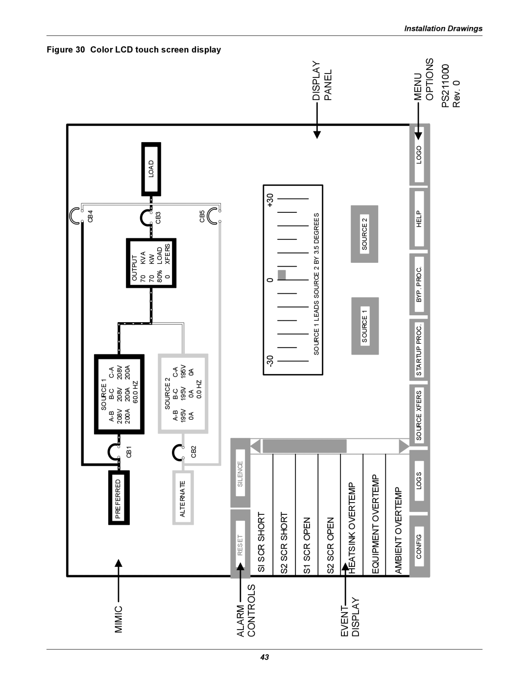
Figure 30
ColorLCD LOAD 
 touch screendisplay
![]() DISPLAY
DISPLAY
PANEL
LOGO ![]()
![]() MENU
MENU
OPTIONS
PS211000
Rev. 0
Installation Drawings