Installation Drawings
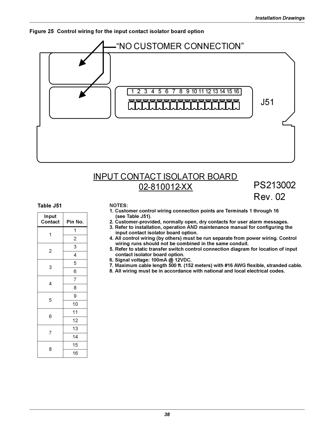
Figure 25 Control wiring for the input contact isolator board option
![]() “NO CUSTOMER CONNECTION”
“NO CUSTOMER CONNECTION”
1 2 3 4 5 6 7 8 9 10 11 12 13 14 15 16
J51
INPUT CONTACT ISOLATOR BOARD
Rev. 02
Table J51
Input
Contact Pin No.
NOTES:
1. | Customer control wiring connection points are Terminals 1 through 16 |
| (see Table J51). |
2. | |
3. | Refer to installation, operation AND maintenance manual for configuring the |
1
2
3
4
5
1
2
3
4
5
6
7
8
9
| input contact isolator board option. |
4. | All control wiring (by others) must be run separate from power wiring. Control |
| wiring runs should not be combined in the same conduit. |
5. | Refer to static transfer switch control connection diagram for location of input |
| contact isolator board option. |
6. | Signal voltage: 100mA @ 12VDC. |
7. Maximum cable length 500 ft. (152 meters) with #16 AWG flexible, stranded cable. | |
8. | All wiring must be in accordance with national and local electrical codes. |
6
7
8
10
11
12
13
14
15
16
38