Installation Drawings
7.0INSTALLATION DRAWINGS
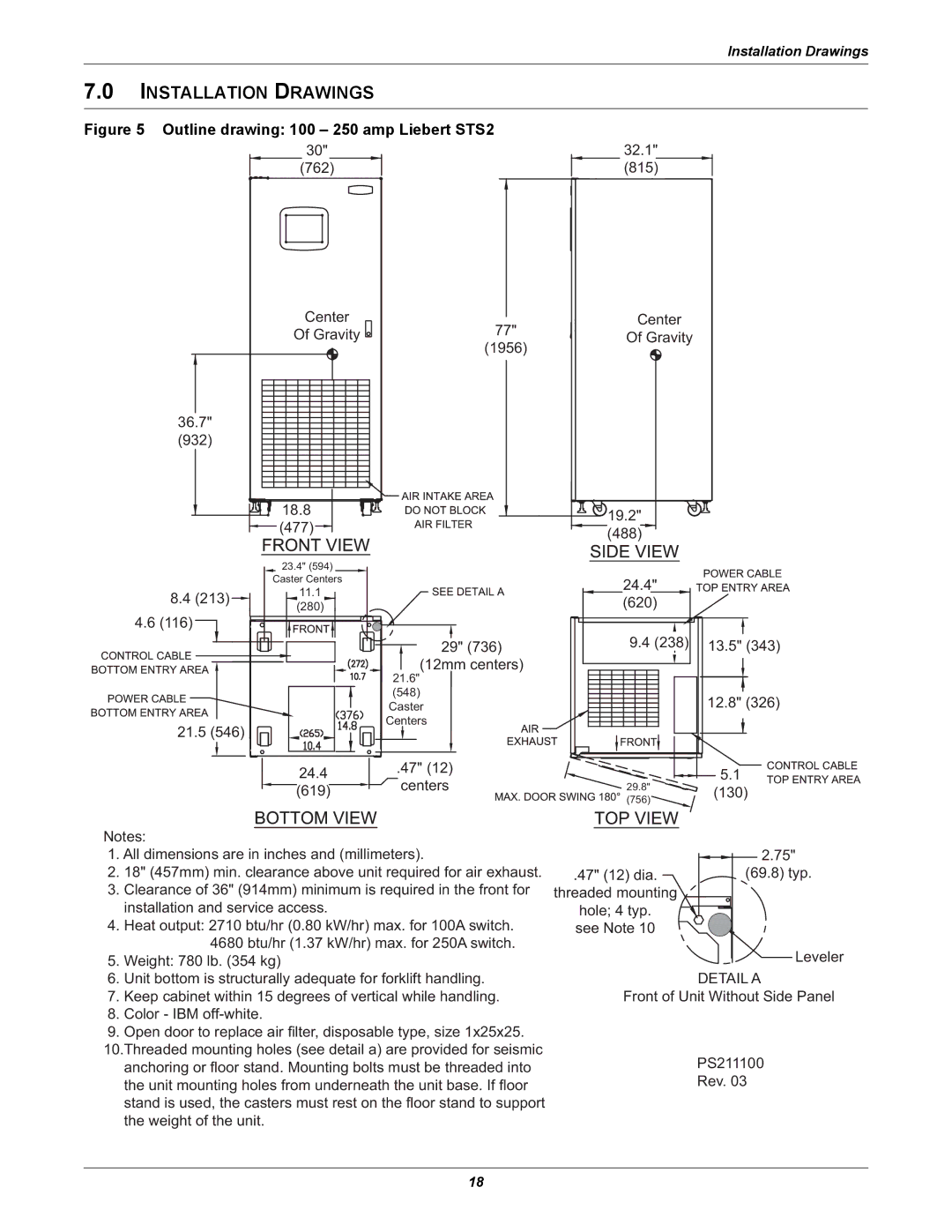
Figure 5 Outline drawing: 100 – 250 amp Liebert STS2
| 30" |
|
| (762) |
|
| Center | 77" |
| Of Gravity | |
|
| (1956) |
36.7" |
|
|
(932) |
|
|
| 18.8 |
|
| (477) |
|
| 23.4" (594) |
|
| Caster Centers |
|
8.4 (213) | 11.1 |
|
(280) |
| |
4.6 (116) |
| |
|
| |
|
| 29" (736) |
|
| (12mm centers) |
|
| 21.6" |
|
| (548) |
|
| Caster |
21.5 (546) |
| Centers |
|
| |
| 24.4 | .47" (12) |
| centers | |
| (619) | |
|
|
32.1"
(815)
Center
Of Gravity
19.2"
(488)
24.4"
(620)
|
|
| 9.4 (238) |
|
| 13.5" (343) | ||||||||
|
|
|
|
|
|
|
|
|
|
|
|
|
|
|
|
|
|
|
|
|
|
|
|
|
|
|
| ||
|
|
|
|
|
|
|
|
|
|
|
|
| ||
|
|
|
|
|
|
|
|
|
| 12.8" (326) | ||||
|
|
|
|
|
|
|
|
|
|
|
|
|
|
|
|
|
|
|
|
|
|
|
|
|
|
|
|
|
|
|
|
|
|
|
|
|
|
|
|
|
|
|
|
|
|
|
|
|
|
|
|
|
|
|
|
|
|
|
|
|
|
|
|
|
|
|
|
|
|
|
|
|
|
|
|
|
|
|
|
|
|
|
|
|
|
|
|
|
|
|
|
|
|
|
|
|
|
|
|
|
|
|
|
|
|
|
|
|
|
|
|
|
|
|
|
|
|
|
|
|
|
|
|
|
|
|
|
|
|
|
|
|
|
|
5.1
29.8" | (130) | |
(756) | ||
|
Notes:
1.All dimensions are in inches and (millimeters).
2.18" (457mm) min. clearance above unit required for air exhaust.
3.Clearance of 36" (914mm) minimum is required in the front for installation and service access.
4.Heat output: 2710 btu/hr (0.80 kW/hr) max. for 100A switch. 4680 btu/hr (1.37 kW/hr) max. for 250A switch.
5.Weight: 780 lb. (354 kg)
6.Unit bottom is structurally adequate for forklift handling.
7.Keep cabinet within 15 degrees of vertical while handling.
8.Color - IBM
9.Open door to replace air filter, disposable type, size 1x25x25. 10.Threaded mounting holes (see detail a) are provided for seismic anchoring or floor stand. Mounting bolts must be threaded into
the unit mounting holes from underneath the unit base. If floor stand is used, the casters must rest on the floor stand to support the weight of the unit.
| 2.75" |
.47" (12) dia. | (69.8) typ. |
threaded mounting
hole; 4 typ. see Note 10
Leveler
DETAIL A
Front of Unit Without Side Panel
PS211100
Rev. 03
18