CHAPTER 3: COMMUNICATIONS
The printer may be connected to PC's,
3.1CABLE PINOUT
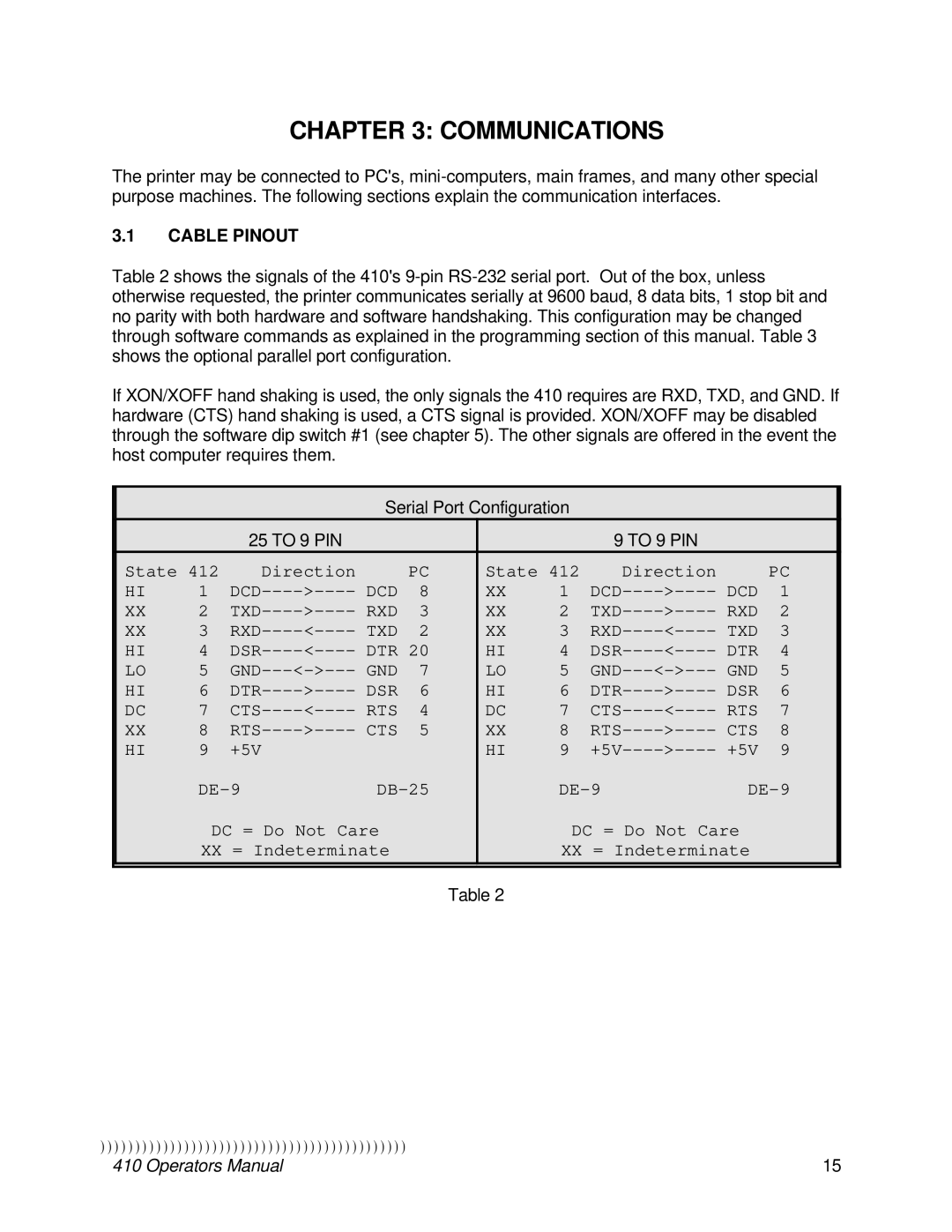
Table 2 shows the signals of the 410's
If XON/XOFF hand shaking is used, the only signals the 410 requires are RXD, TXD, and GND. If hardware (CTS) hand shaking is used, a CTS signal is provided. XON/XOFF may be disabled through the software dip switch #1 (see chapter 5). The other signals are offered in the event the host computer requires them.
Serial Port Configuration
|
|
| 25 TO 9 PIN |
|
|
|
| 9 TO 9 PIN |
|
|
| ||
| State 412 |
| Direction |
| PC | State 412 | Direction |
| PC |
| |||
| HI | 1 | DCD | DCD | 8 | XX | 1 | DCD | DCD | 1 |
| ||
| XX | 2 | TXD | RXD | 3 | XX | 2 | TXD | RXD | 2 |
| ||
| XX | 3 | RXD | TXD | 2 | XX | 3 | RXD | TXD | 3 |
| ||
| HI | 4 | DSR | DTR 20 | HI | 4 | DSR | DTR | 4 |
| |||
| LO | 5 | GND | GND | 7 | LO | 5 | GND | GND | 5 |
| ||
| HI | 6 | DTR | DSR | 6 | HI | 6 | DTR | DSR | 6 |
| ||
| DC | 7 | CTS | RTS | 4 | DC | 7 | CTS | RTS | 7 |
| ||
| XX | 8 | RTS | CTS | 5 | XX | 8 | RTS | CTS | 8 |
| ||
| HI | 9 | +5V |
|
|
| HI | 9 | +5V | +5V | 9 |
| |
|
|
|
|
|
|
|
| ||||||
|
| DC = Do Not Care |
|
|
| DC = Do Not Care |
|
| |||||
|
| XX = Indeterminate |
|
| XX = Indeterminate |
|
| ||||||
|
|
|
|
|
|
|
|
|
|
|
|
|
|
Table 2
))))))))))))))))))))))))))))))))))))))))))))
410 Operators Manual | 15 |
