Installation and Operation, cont’d
Furniture or projector mounting
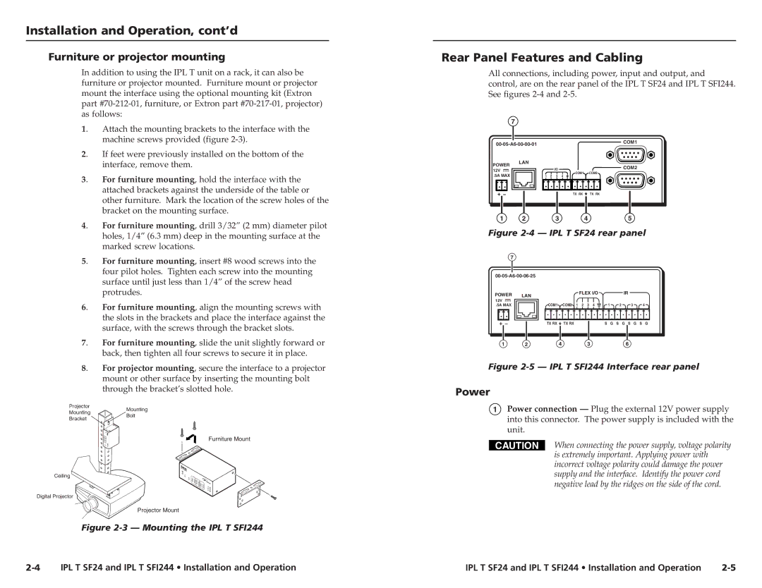
In addition to using the IPL T unit on a rack, it can also be furniture or projector mounted. Furniture mount or projector mount the interface using the optional mounting kit (Extron part
1. | Attach the mounting brackets to the interface with the |
| machine screws provided (figure |
2. | If feet were previously installed on the bottom of the |
| interface, remove them. |
3. | For furniture mounting, hold the interface with the |
| attached brackets against the underside of the table or |
| other furniture. Mark the location of the screw holes of the |
| bracket on the mounting surface. |
4. | For furniture mounting, drill 3/32” (2 mm) diameter pilot |
| holes, 1/4” (6.3 mm) deep in the mounting surface at the |
| marked screw locations. |
5. | For furniture mounting, insert #8 wood screws into the |
| four pilot holes. Tighten each screw into the mounting |
| surface until just less than 1/4” of the screw head |
| protrudes. |
6. | For furniture mounting, align the mounting screws with |
| the slots in the brackets and place the interface against the |
| surface, with the screws through the bracket slots. |
7. | For furniture mounting, slide the unit slightly forward or |
| back, then tighten all four screws to secure it in place. |
8. | For projector mounting, secure the interface to a projector |
| mount or other surface by inserting the mounting bolt |
| through the bracket’s slotted hole. |
Rear Panel Features and Cabling
All connections, including power, input and output, and control, are on the rear panel of the IPL T SF24 and IPL T SFI244. See figures
7
| COM1 | ||
|
| ||
POWER | LAN |
| COM2 |
| I/O | ||
12V |
| ||
| COM1 | COM2 | |
.5A MAX |
| ||
| 1 2 3 4 |
| |
|
| TX RX | TX RX |
1 | 2 | 3 | 4 | 5 |
Figure 2-4 — IPL T SF24 rear panel
7
POWER | LAN | FLEX I/O |
| IR |
|
|
|
|
|
|
| ||
12V |
| COM2 1 2 3 4 | 1 | 2 | 3 | 4 |
.5A MAX | COM1 | |||||
| TX RX | TX RX | S G | S G S | G | S G |
1 | 2 | 4 | 3 | 6 |
Figure 2-5 — IPL T SFI244 Interface rear panel
Power
Projector
Mounting
Bracket
Ceiling
Digital Projector
Mounting
Bolt
Furniture Mount
Projector Mount
1Power connection — Plug the external 12V power supply into this connector. The power supply is included with the unit.
CAUTION | When connecting the power supply, voltage polarity |
| is extremely important. Applying power with |
| incorrect voltage polarity could damage the power |
| supply and the interface. Identify the power cord |
| negative lead by the ridges on the side of the cord. |
Figure 2-3 — Mounting the IPL T SFI244
IPL T SF24 and IPL T SFI244 • Installation and Operation | IPL T SF24 and IPL T SFI244 • Installation and Operation |