Communication and Control, cont’d
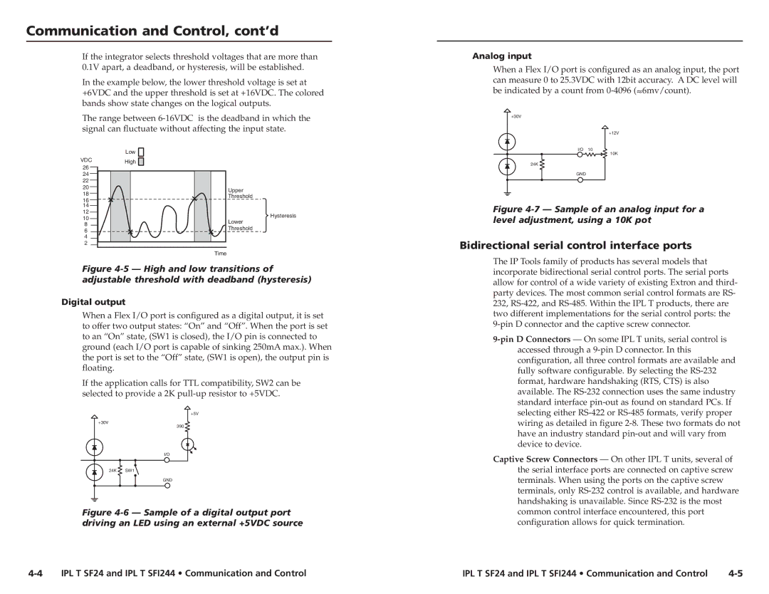
If the integrator selects threshold voltages that are more than 0.1V apart, a deadband, or hysteresis, will be established.
In the example below, the lower threshold voltage is set at +6VDC and the upper threshold is set at +16VDC. The colored bands show state changes on the logical outputs.
The range between
| Low | |
VDC | High | |
26 | ||
| ||
24 |
| |
22 |
| |
20 | Upper | |
18 | ||
Threshold | ||
16 | ||
| ||
14 |
| |
12 | Hysteresis | |
10 | ||
Lower | ||
8 | ||
Threshold | ||
6 | ||
| ||
4 |
| |
2 |
| |
| Time |
Figure 4-5 — High and low transitions of adjustable threshold with deadband (hysteresis)
Digital output
When a Flex I/O port is configured as a digital output, it is set to offer two output states: “On” and “Off”. When the port is set to an “On” state, (SW1 is closed), the I/O pin is connected to ground (each I/O port is capable of sinking 250mA max.). When the port is set to the “Off” state, (SW1 is open), the output pin is floating.
If the application calls for TTL compatibility, SW2 can be selected to provide a 2K
+5V
+30V
390
I/O
24K SW1 ![]()
GND
Figure 4-6 — Sample of a digital output port driving an LED using an external +5VDC source
Analog input
When a Flex I/O port is configured as an analog input, the port can measure 0 to 25.3VDC with 12bit accuracy. A DC level will be indicated by a count from ![]() 6mv/count).
6mv/count).
+30V
+12V
I/O 10
10K
24K
GND
Figure 4-7 — Sample of an analog input for a level adjustment, using a 10K pot
Bidirectional serial control interface ports
The IP Tools family of products has several models that incorporate bidirectional serial control ports. The serial ports allow for control of a wide variety of existing Extron and third- party devices. The most common serial control formats are RS- 232,
Captive Screw Connectors — On other IPL T units, several of the serial interface ports are connected on captive screw terminals. When using the ports on the captive screw terminals, only
IPL T SF24 and IPL T SFI244 • Communication and Control | IPL T SF24 and IPL T SFI244 • Communication and Control |