Installation and Operation, cont’d
AA
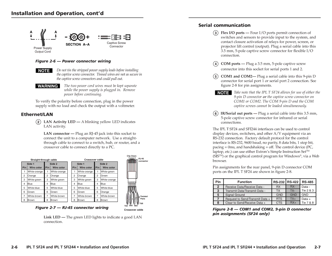
| SECTION | Captive Screw | |
Power Supply | Connector | ||
| |||
|
| ||
Output Cord |
|
|
Figure 2-6 — Power connector wiring
Do not tin the stripped power supply leads before installing the captive screw connector. Tinned wires are not as secure in the captive screw connectors and could pull out.
The two power cord wires must be kept separate while the power supply is plugged in. Remove power before continuing.
To verify the polarity before connection, plug in the power supply with no load and check the output with a voltmeter.
Ethernet/LAN
2LAN Activity LED — A blinking yellow LED indicates LAN activity.
LAN connector — Plug an
Clip Down
|
| Crossover cable | 1 2 3 4 5 6 7 8 | |||||||
|
|
|
| |||||||
|
|
|
| connector | ||||||
|
|
|
|
|
|
|
|
|
| |
| Side 1 |
| Side 2 |
| Side 1 |
| Side 2 |
|
|
|
Pin | Wire color | Pin | Wire color | Pin | Wire color | Pin | Wire color |
|
|
|
1 | 1 | 1 | 1 |
|
|
| ||||
2 | Orange | 2 | Orange | 2 | Orange | 2 | Green |
|
|
|
3 | 3 | 3 | 3 |
|
|
| ||||
4 | Blue | 4 | Blue | 4 | Blue | 4 | Blue | 1 2 3 4 5 6 7 8 |
| |
|
|
| ||||||||
5 | 5 | 5 | 5 |
|
|
| ||||
6 | Green | 6 | Green | 6 | Green | 6 | Orange |
|
|
|
7 | 7 | 7 | 7 |
|
| Twisted | ||||
8 | Brown | 8 | Brown | 8 | Brown | 8 | Brown |
|
| Pairs |
|
|
| ||||||||
|
|
|
|
|
|
|
| 1&2 3&6 | 4&5 | 7&8 |
| Figure |
| ||||||||
| Crossover cable | |||||||||
|
|
|
|
|
|
|
| |||
Link LED — The green LED lights to indicate a good LAN connection.
Serial communication
3Flex I/O ports — Four I/O ports permit connection of switches and sensors to provide input to the system, and contact closure activation of relays for power, screen, or projector lift control (output). Plug a serial cable into this 3.5 mm,
4COM ports — Plug a 3.5 mm,
5COM1 and COM2— Plug a serial cable into this
Take note that the IPL T SF24 allows for use of either the
6IR/Serial out ports — Plug a serial cable into this 3.5 mm,
The IPL T SF24 and SFI244 interfaces can be used to control display devices, switchers, and other A/V equipment via an
Pin assignments for the rear panel,
Pin | Function |
|
|
|
2 | Receive Data/Receive Data - | RX | RX- | Data - |
3 | Transmit Data/Transmit Data - | TX | TX- | Tie 2 & 3 |
5 | Signal Ground | GND | GND | GND |
7 | Request to Send/Transmit Data + | RTS | TX+ | Data + |
8 | Clear to Send/Receive Data + | CTS | RX+ | Tie 7 & 8 |
Figure 2-8 — COM1 and COM2, 9-pin D connector pin assignments (SF24 only)
IPL T SF24 and IPL T SFI244 • Installation and Operation | IPL T SF24 and IPL T SFI244 • Installation and Operation |