Connection and Configuration, cont’d
Connecting the Hardware
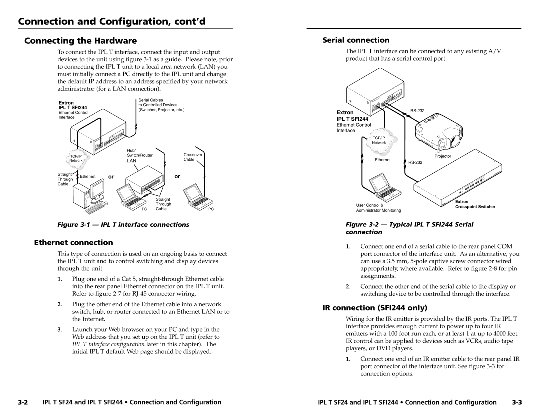
To connect the IPL T interface, connect the input and output devices to the unit using figure
Extron | Serial Cables | |
to Controlled Devices | ||
IPL T SFI244 | ||
(Switcher, Projector, etc.) | ||
Ethernet Control | ||
|
Serial connection
The IPL T interface can be connected to any existing A/V product that has a serial control port.
|
|
|
|
|
| IR |
|
|
|
|
|
| I/O |
|
|
|
|
|
| FLEX |
|
|
|
| xx- | xx- | xx |
|
|
| A6- |
| ||
| 00- | 05- |
|
|
| |
|
|
|
|
|
| |
|
|
|
| LAN | ||
| POWER |
|
|
| ||
| 12V MAX |
|
| |||
Extron | .5A |
|
|
|
| |
|
|
|
|
| ||
Interface |
|
|
|
|
|
|
|
|
|
|
| IR |
|
|
|
|
|
| I/O |
|
|
|
|
|
| FLEX |
|
|
|
|
|
| ||
|
|
|
|
| ||
|
|
|
|
|
| |
|
|
|
| LAN |
| |
| POWER |
|
|
|
| |
| 12V MAX |
|
|
|
| |
| .5A |
|
|
| Hub/ |
|
|
|
|
|
| Crossover | |
TCP/IP |
|
|
| Switch/Router | ||
Network |
|
|
| LAN | Cable | |
Straight | Ethernet |
|
|
| or | or |
Through |
|
|
| |||
|
|
|
|
|
| |
Cable |
|
|
|
|
|
|
|
|
|
|
|
| Straight |
IPL T SFI244
Ethernet Control
Interface
TCP/IP
Network
Ethernet
Projector
| Through |
|
PC | Cable | PC |
Figure 3-1 — IPL T interface connections
Ethernet connection
This type of connection is used on an ongoing basis to connect the IPL T unit and to control switching and display devices through the unit.
1. | Plug one end of a Cat 5, |
| into the rear panel Ethernet connector on the IPL T unit. |
| Refer to figure |
2. | Plug the other end of the Ethernet cable into a network |
| switch, hub, or router connected to an Ethernet LAN or to |
| the Internet. |
3. | Launch your Web browser on your PC and type in the |
| Web address that you set up on the IPL T unit (refer to |
| IPL T interface configuration later in this chapter). The |
| initial IPL T default Web page should be displayed. |
| User Control & | Extron |
| Crosspoint Switcher | |
| Administrator Monitoring | |
|
| |
Figure | ||
connection |
| |
1. | Connect one end of a serial cable to the rear panel COM | |
| port connector of the interface unit. As an alternative, you | |
| can use a 3.5 mm, | |
| appropriately, where available. Refer to figure | |
| assignments. |
|
2. | Connect the other end of the serial cable to the display or | |
| switching device to be controlled through the interface. | |
IR connection (SFI244 only)
Wiring for the IR emitter is provided by the IR ports. The IPL T interface provides enough current to power up to four IR emitters with a 100 foot run each, or at least 1 at up to 4000 feet. IR control can be applied to devices such as VCRs, audio tape players, or DVD players.
1. | Connect one end of an IR emitter cable to the rear panel IR |
| port connector of the interface unit. See figure |
| connection options. |
IPL T SF24 and IPL T SFI244 • Connection and Configuration | IPL T SF24 and IPL T SFI244 • Connection and Configuration |