Connection and Configuration, cont’d
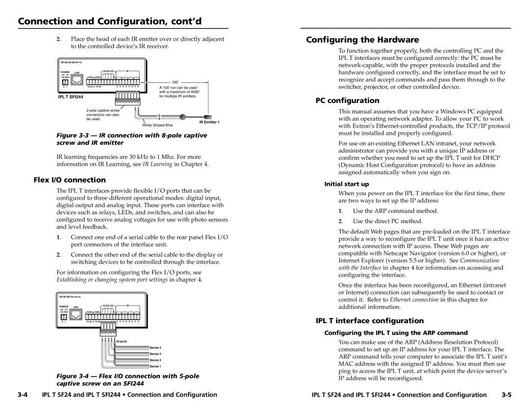
2. | Place the head of each IR emitter over or directly adjacent |
| to the controlled device’s IR receiver. |
Configuring the Hardware
POWER LAN
12V
.5A MAX
IPL T SFI244
| FLEX I/O |
| IR |
|
COM1 | COM2 1 2 3 4 | 1 | 2 3 4 |
|
|
|
|
| 100' |
TX RX | TX RX | S G | S G S G S G | A 100' run can be used |
|
|
|
| |
|
|
|
| with a maximum of 4000' |
|
|
|
| for multiple IR emitters. |
|
| |||
connectors can also |
| G | ||
be used. |
|
| S | |
IR Emitter 1
White Striped Wire
To function together properly, both the controlling PC and the IPL T interfaces must be configured correctly: the PC must be
PC configuration
This manual assumes that you have a Windows PC equipped with an operating network adapter. To allow your PC to work with Extron’s
Figure 3-3 — IR connection with 8-pole captive screw and IR emitter
IR learning frequencies are 30 kHz to 1 Mhz. For more information on IR Learning, see IR Learning in Chapter 4.
Flex I/O connection
The IPL T interfaces provide flexible I/O ports that can be configured to three different operational modes: digital input, digital output and analog input. These ports can interface with devices such as relays, LEDs, and switches, and can also be configured to receive analog voltages for use with photo sensors and level feedback.
1. | Connect one end of a serial cable to the rear panel Flex I/O |
| port connectors of the interface unit. |
2. | Connect the other end of the serial cable to the display or |
| switching devices to be controlled through the interface. |
For information on configuring the Flex I/O ports, see
Establishing or changing system port settings in chapter 4.
POWER | LAN | FLEX I/O |
| IR |
|
|
12V |
|
|
|
|
|
|
.5A MAX | COM1 | COM2 1 2 3 4 | 1 | 2 | 3 | 4 |
| TX RX | TX RX | S G | S G S | G | S G |
Ground
Device 4
Device 3
Device 2
Device 1
Figure 3-4 — Flex I/O connection with 5-pole captive screw on an SFI244
For use on an existing Ethernet LAN intranet, your network administrator can provide you with a unique IP address or confirm whether you need to set up the IPL T unit for DHCP (Dynamic Host Configuration protocol) to have an address assigned automatically when you sign on.
Initial start up
When you power on the IPL T interface for the first time, there are two ways to set up the IP address:
1. Use the ARP command method.
2. Use the direct PC method.
The default Web pages that are
Once the interface has been reconfigured, an Ethernet (intranet or Internet) connection can subsequently be used to contact or control it. Refer to Ethernet connection in this chapter for additional information.
IPL T interface configuration
Configuring the IPL T using the ARP command
You can make use of the ARP (Address Resolution Protocol) command to set up an IP address for your IPL T interface. The ARP command tells your computer to associate the IPL T unit’s MAC address with the assigned IP address. You must then use ping to access the IPL T unit, at which point the device server’s IP address will be reconfigured.
IPL T SF24 and IPL T SFI244 • Connection and Configuration |
