Genlock connections
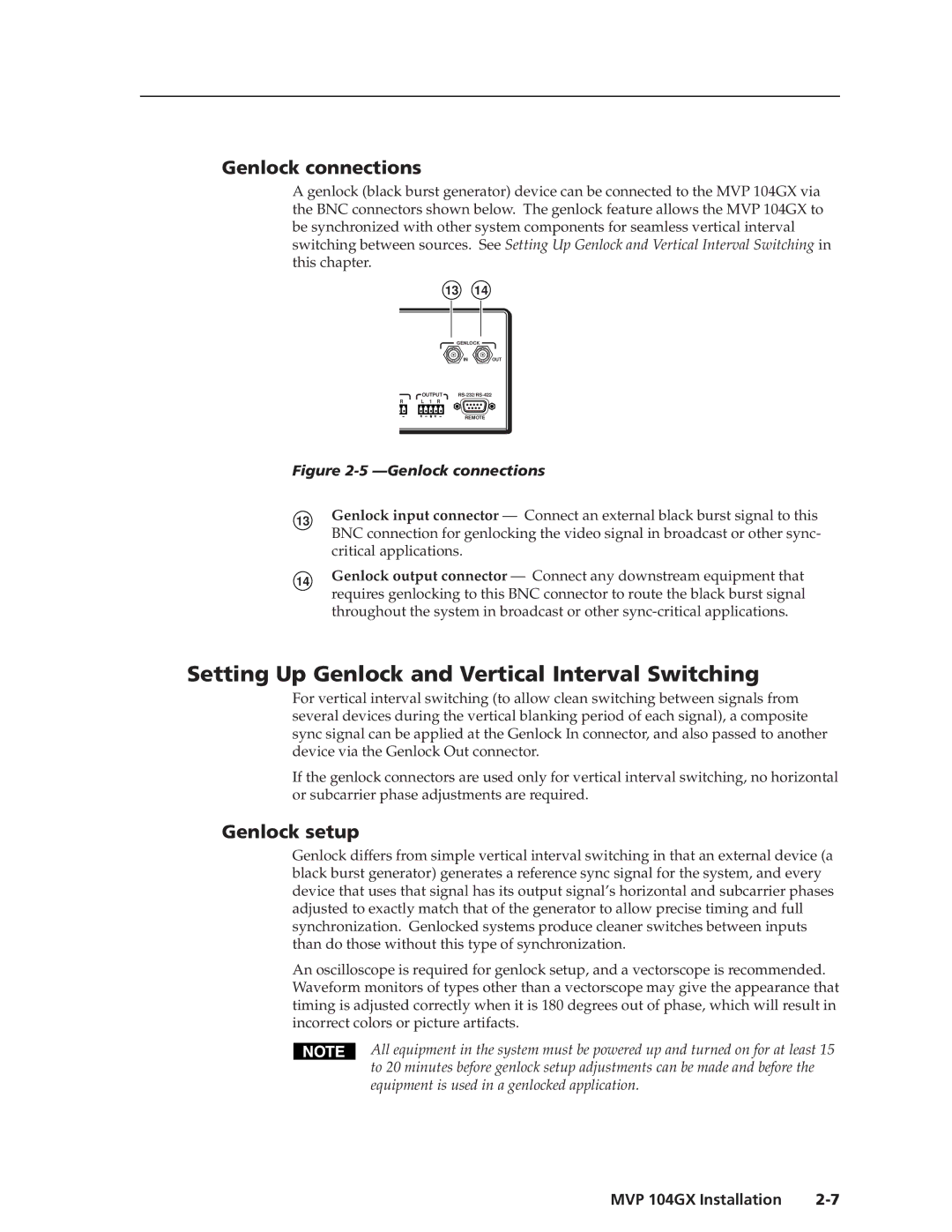
A genlock (black burst generator) device can be connected to the MVP 104GX via the BNC connectors shown below. The genlock feature allows the MVP 104GX to be synchronized with other system components for seamless vertical interval switching between sources. See Setting Up Genlock and Vertical Interval Switching in this chapter.
13 14
GENLOCK
IN ![]() OUT
OUT
| OUTPUT | |
R | L 1 R |
|
REMOTE
Figure 2-5 —Genlock connections
13Genlock input connector — Connect an external black burst signal to this BNC connection for genlocking the video signal in broadcast or other sync- critical applications.
14Genlock output connector — Connect any downstream equipment that requires genlocking to this BNC connector to route the black burst signal throughout the system in broadcast or other
Setting Up Genlock and Vertical Interval Switching
For vertical interval switching (to allow clean switching between signals from several devices during the vertical blanking period of each signal), a composite sync signal can be applied at the Genlock In connector, and also passed to another device via the Genlock Out connector.
If the genlock connectors are used only for vertical interval switching, no horizontal or subcarrier phase adjustments are required.
Genlock setup
Genlock differs from simple vertical interval switching in that an external device (a black burst generator) generates a reference sync signal for the system, and every device that uses that signal has its output signal’s horizontal and subcarrier phases adjusted to exactly match that of the generator to allow precise timing and full synchronization. Genlocked systems produce cleaner switches between inputs than do those without this type of synchronization.
An oscilloscope is required for genlock setup, and a vectorscope is recommended. Waveform monitors of types other than a vectorscope may give the appearance that timing is adjusted correctly when it is 180 degrees out of phase, which will result in incorrect colors or picture artifacts.
All equipment in the system must be powered up and turned on for at least 15 to 20 minutes before genlock setup adjustments can be made and before the equipment is used in a genlocked application.
MVP 104GX Installation |