Installation, cont’d
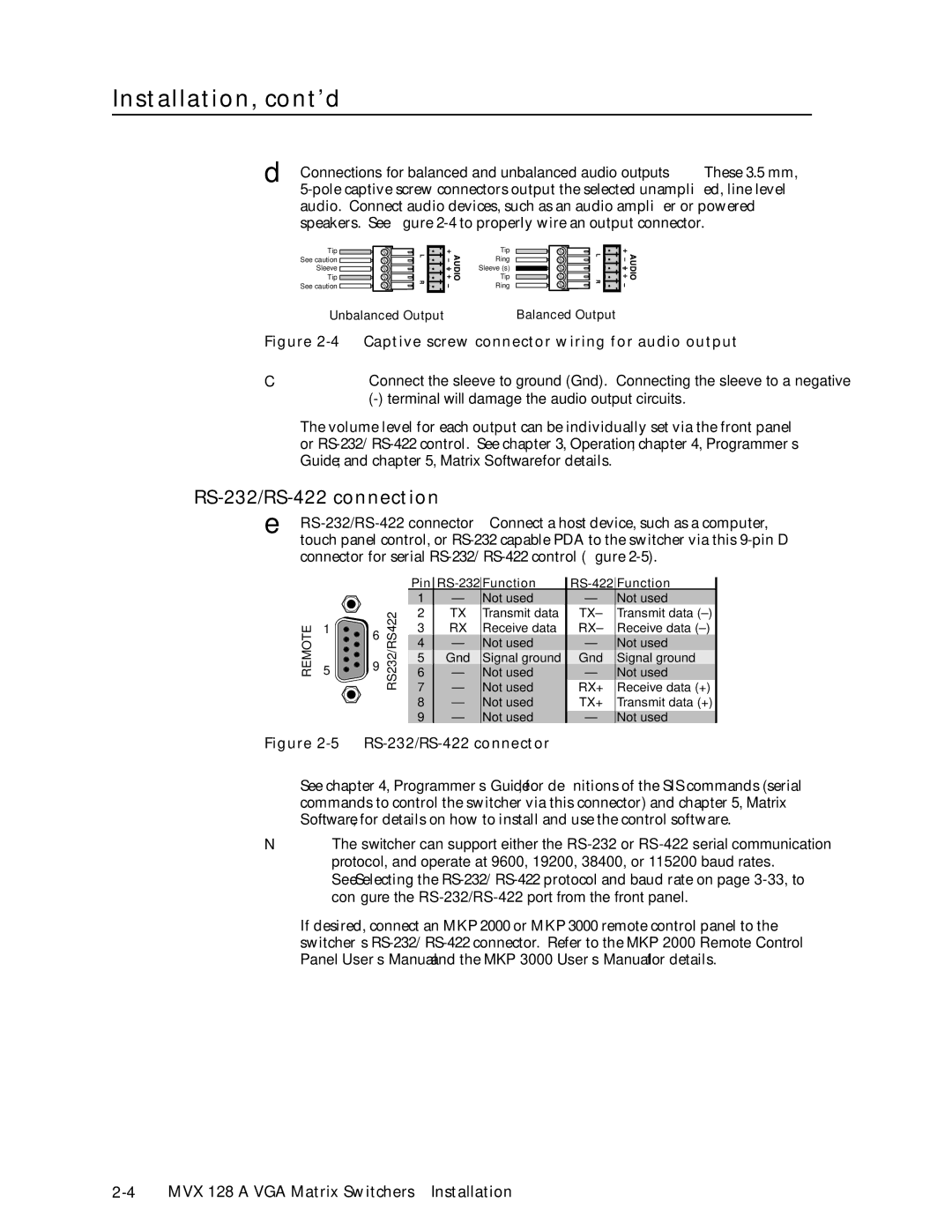
d Connections for balanced and unbalanced audio outputs — These 3.5 mm,
Tip ![]() See caution
See caution ![]() Sleeve
Sleeve ![]() Tip
Tip ![]()
See caution ![]()
Tip
Ring
Sleeve (s)
Tip
Ring
Unbalanced Output | Balanced Output |
Figure 2-4 — Captive screw connector wiring for audio output
CConnect the sleeve to ground (Gnd). Connecting the sleeve to a negative
The volume level for each output can be individually set via the front panel or
RS-232/RS-422 connection
e
REMOTE
|
|
| Pin | |||||
|
|
| 1 | — | Not used | — | Not used | |
|
| RS232/RS422 | 2 | TX | Transmit data | TX– | Transmit data | |
1 | 6 | 3 | RX | Receive data | RX– | Receive data | ||
| ||||||||
|
| 4 | — | Not used | — | Not used | ||
|
|
| ||||||
5 | 9 |
| 5 | Gnd | Signal ground | Gnd | Signal ground | |
| 6 | — | Not used | — | Not used | |||
|
| |||||||
|
|
| 7 | — | Not used | RX+ | Receive data (+) | |
|
|
| 8 | — | Not used | TX+ | Transmit data (+) | |
|
|
| 9 | — | Not used | — | Not used | |
Figure 2-5 — RS-232/RS-422 connector
See chapter 4, Programmer’s Guide, for definitions of the SIS commands (serial commands to control the switcher via this connector) and chapter 5, Matrix Software, for details on how to install and use the control software.
NThe switcher can support either the
See Selecting the
If desired, connect an MKP 2000 or MKP 3000 remote control panel to the switcher’s