VGA Matrix Switcher
MVX 128 a
Precautions
Safety Instructions English
Consignes de Sécurité Français
Sicherheitsanleitungen Deutsch
Plug the switcher into a grounded AC source
Quick Start MVX 128 a VGA Matrix Switchers
MVX 128 a VGA Matrix Switchers Quick Start QS-1
Saving or recalling a preset
Viewing and adjusting the audio level
QS-2 MVX 128 a VGA Matrix Switchers Quick Start
Create a tie
Table of Contents
Table of Contents, cont’d
One
About the MVX 128 a Matrix Switcher
MVX 128 a VGA Matrix Switchers Introduction
Introduction
About this Manual
Definitions
Features
Introduction, cont’d
MVX 128 a VGA Matrix Switchers Introduction
Introduction, cont’d
Two
Installation
Mounting the Switcher
MVX 128 a VGA Matrix Switchers Installation
Cabling and Rear Panel Views
Captive screw connector wiring for audio inputs
Audio connections
Installation, cont’d
RS-232/RS-422 connection
Reset button
Power connection
Installation, cont’d
Three
Front Panel Controls and Indicators
MVX 128 a VGA Matrix Switchers Operation
Operation
Definitions
Input and output buttons
Sample label
Operation, cont’d
Control buttons
See Viewing and adjusting the input audio level on
Controls
Power
Front Panel Operations
Creating a configuration
Press and release the Esc button figure
Example 1 Creating a set of video and audio ties
Press and release the input 5 button figure
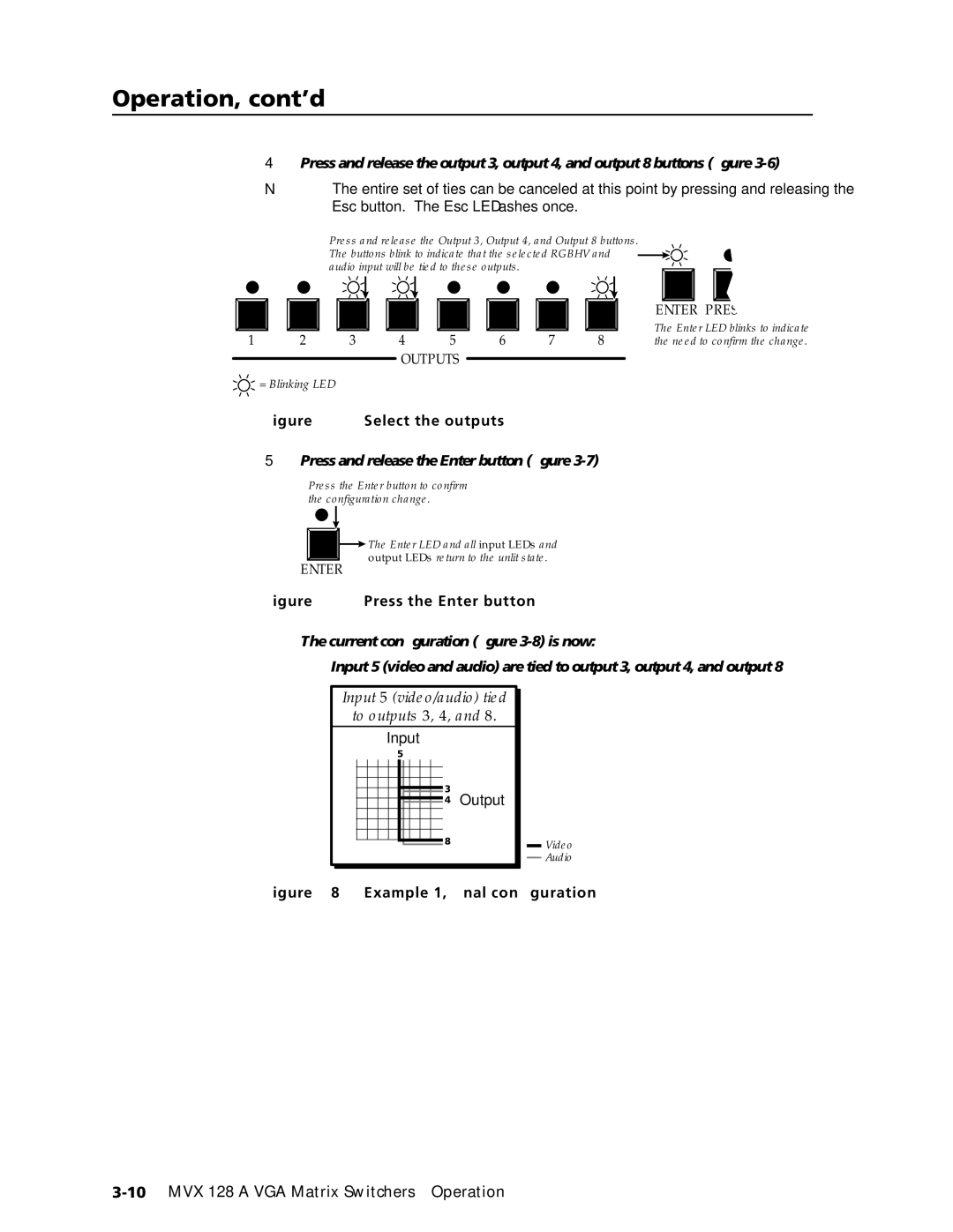
Select the outputs
Press and release the Enter button figure
Example 2 Adding a tie to a set of video and audio ties
This example assumes that you have performed example
13 Press the Enter button
Example 3 Removing a tie from a set of video and audio ties
15 Clear all selections
18 Deselect the output
Viewing a configuration
21 Clear all selections
Rgbhv button and the Audio button figure
22 Select Rgbhv or video and audio
Press and release the Rgbhv button to deselect Rgbhv figure
Video Audio
Muting and unmuting video and/or audio
Example 5 Muting and unmuting an output
28 Select Rgbhv and audio
30 Unmute the outputs
Using global presets
Example 6 Saving a preset
LED blinks figure
Press and release the Output 1 button figure
Example 7 Recalling a preset
Press and release the Preset button figure
Viewing and adjusting the input audio level
40 Press the Enter button
DB when blinking slowly, 2 dB
When blinking quickly, and 3 dB
When lit. See the table at right
Press and release an input button
Example 10 Viewing and adjusting an input audio level
42 Clear all selections
Press and release the Audio button figure
View View ESC Outputs
Released or the upper or lower limit is reached
Viewing and adjusting the output volume
Audio mode. The Audio button stops blinking
Reading the displayed volume
Audio output volume settings
Example 11 Viewing and adjusting an output volume level
47 Clear all selections
49 Select output
Locking out the front panel Executive mode
Performing a system reset from the front panel
Enter Preset View ESC Rgbhv Audio
Selecting the RS-232/RS-422 protocol and baud rate
Rear Panel Operations
Performing an absolute system reset from the rear panel
Not occur within 1 second
Performing a hard reset from the rear panel
Optimizing the Audio
Configuration Worksheets
Troubleshooting
Worksheet example 1 System equipment
Worksheet example 2 Daily configuration
Audio
Worksheet example 3 Test configuration
61 Worksheet example 3 Test configuration
Output destinations
Configuration worksheet
Operation, cont’d
Four
Host-to-Switcher Instructions
Switcher-Initiated Messages
MVX 128 a VGA Matrix Switchers Programmer’s Guide
Programmer’s Guide
Switcher Error Responses
Using the Command/Response Tables
Command/Response Table for SIS Commands
Symbol definitions
X1 =
X1@ =
Command Ascii command Response Additional
Description
% G InX! AudX$
Audio volume adjustment settings
EX!NI
EZG
X1* CY
X1X1X1X1X1X2
Information requests
Programmer’s Guide, cont’d
Five
Matrix Switchers Control Program
Installing the software
MVX 128 a VGA Matrix Switchers Matrix Software
Matrix Software
Using the software
Click OK and proceed to step
Matrix Software, cont’d
Updating firmware
Open file window
Click the Exit button to exit the firmware loader utility
Windows menus
Windows buttons, drop boxes, and trashcan
File menu
Audio-Output volume settings Displays the audio
Tools menu
Preferences menu
Ties shown as lines
Using emulation mode
Using the help system
Master-Reset selection
Button-Label Generator Program
AppendixAA
Specifications, Part Numbers, Accessories
Specifications
Audio
Specifications, Part Numbers, Accessories, cont’d
Part Numbers and Accessories
Accessories
Included parts Replacement part Number
Adapters, power supplies, labels Part number
Male-to-female VGA molded connector cables Part number
Male-to-female VGA backshell connector cables Part number
Male-to-male VGA molded connector cables Part number
Cables
Button Labels
Figure A-1 Button label blanks, 12-button strips
Specifications, Part Numbers, Accessories, cont’d
FCC Class a Notice Extron’s Warranty
Extron Electronics, Europe
Extron Electronics, USA