Application – Single-Phase Motors
2 or
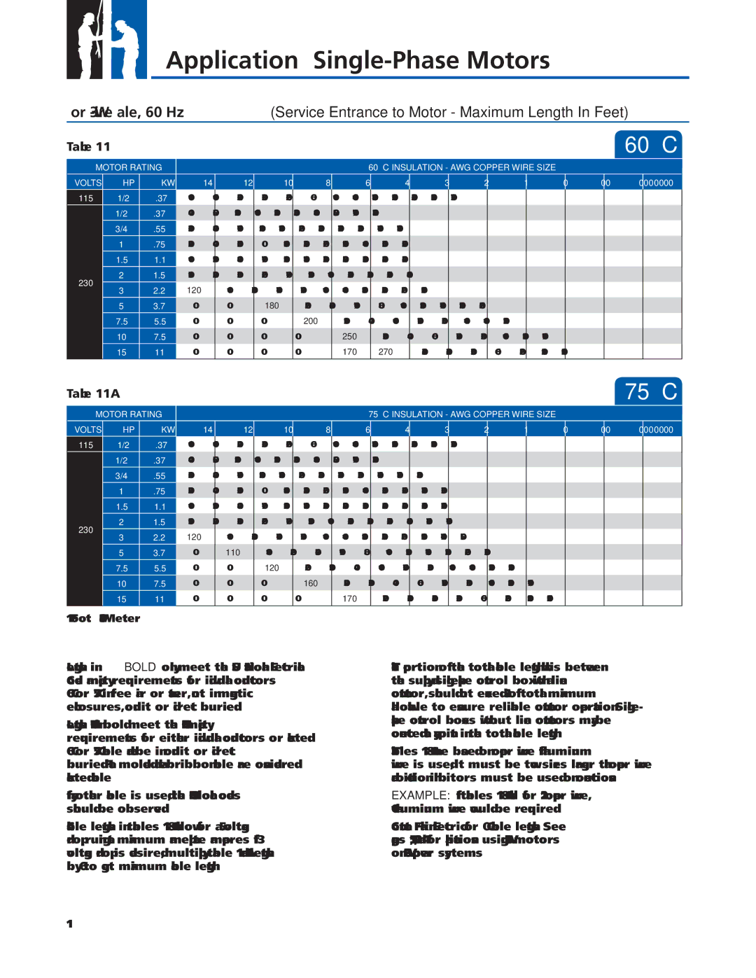
Table 11 |
|
|
|
|
|
|
|
|
|
|
|
| 60 °C | |||
| MOTOR RATING |
|
|
|
|
| 60 °C INSULATION - AWG COPPER WIRE SIZE |
|
|
|
| |||||
|
|
|
|
|
|
|
|
|
| |||||||
VOLTS |
| HP | KW | 14 | 12 | 10 | 8 | 6 | 4 | 3 | 2 | 1 | 0 | 00 | 000 | 0000 |
115 | 1/2 | .37 | 100 | 160 | 250 | 390 | 620 | 960 | 1190 | 1460 | 1780 | 2160 | 2630 | 3140 | 3770 | |
| 1/2 | .37 | 400 | 650 | 1020 | 1610 | 2510 | 3880 | 4810 | 5880 | 7170 | 8720 |
|
|
| |
| 3/4 | .55 | 300 | 480 | 760 | 1200 | 1870 | 2890 | 3580 | 4370 | 5330 | 6470 | 7870 |
|
| |
| 1 | .75 | 250 | 400 | 630 | 990 | 1540 | 2380 | 2960 | 3610 | 4410 | 5360 | 6520 |
|
| |
| 1.5 | 1.1 | 190 | 310 | 480 | 770 | 1200 | 1870 | 2320 | 2850 | 3500 | 4280 | 5240 |
|
| |
230 | 2 | 1.5 | 150 | 250 | 390 | 620 | 970 | 1530 | 1910 | 2360 | 2930 | 3620 | 4480 |
|
| |
3 | 2.2 | 120 | 190 | 300 | 470 | 750 | 1190 | 1490 | 1850 | 2320 | 2890 | 3610 |
|
| ||
|
|
| ||||||||||||||
| 5 | 3.7 | 0 | 0 | 180 | 280 | 450 | 710 | 890 | 1110 | 1390 | 1740 | 2170 | 2680 |
| |
| 7.5 | 5.5 | 0 | 0 | 0 | 200 | 310 | 490 | 610 | 750 | 930 | 1140 | 1410 | 1720 |
| |
| 10 | 7.5 | 0 | 0 | 0 | 0 | 250 | 390 | 490 | 600 | 750 | 930 | 1160 | 1430 | 1760 | |
|
| 15 | 11 | 0 | 0 | 0 | 0 | 170 | 270 | 340 | 430 | 530 | 660 | 820 | 1020 | 1260 |
Table 11A |
|
|
|
|
|
|
|
|
|
|
|
| 75 °C | ||||
| MOTOR RATING |
|
|
|
|
| 75 °C INSULATION - AWG COPPER WIRE SIZE |
|
|
|
| ||||||
|
|
|
|
|
|
|
|
|
| ||||||||
VOLTS |
| HP | KW | 14 | 12 | 10 | 8 | 6 | 4 | 3 | 2 | 1 | 0 | 00 | 000 | 0000 | |
115 | 1/2 | .37 | 100 | 160 | 250 | 390 | 620 | 960 | 1190 | 1460 | 1780 | 2160 | 2630 | 3140 | 3770 | ||
| 1/2 | .37 | 400 | 650 | 1020 | 1610 | 2510 | 3880 | 4810 | 5880 | 7170 | 8720 |
|
|
| ||
| 3/4 | .55 | 300 | 480 | 760 | 1200 | 1870 | 2890 | 3580 | 4370 | 5330 | 6470 | 7870 | 9380 |
| ||
| 1 | .75 | 250 | 400 | 630 | 990 | 1540 | 2380 | 2960 | 3610 | 4410 | 5360 | 6520 | 7780 | 9350 | ||
| 1.5 | 1.1 | 190 | 310 | 480 | 770 | 1200 | 1870 | 2320 | 2850 | 3500 | 4280 | 5240 | 6300 | 7620 | ||
230 | 2 | 1.5 | 150 | 250 | 390 | 620 | 970 | 1530 | 1910 | 2360 | 2930 | 3620 | 4480 | 5470 | 6700 | ||
3 | 2.2 | 120 | 190 | 300 | 470 | 750 | 1190 | 1490 | 1850 | 2320 | 2890 | 3610 | 4470 | 5550 | |||
| |||||||||||||||||
| 5 | 3.7 | 0 | 110 | 180 | 280 | 450 | 710 | 890 | 1110 | 1390 | 1740 | 2170 | 2680 | 3330 | ||
| 7.5 | 5.5 | 0 | 0 | 120 | 200 | 310 | 490 | 610 | 750 | 930 | 1140 | 1410 | 1720 | 2100 | ||
| 10 | 7.5 | 0 | 0 | 0 | 160 | 250 | 390 | 490 | 600 | 750 | 930 | 1160 | 1430 | 1760 | ||
| 15 | 11 | 0 | 0 | 0 | 0 | 170 | 270 | 340 | 430 | 530 | 660 | 820 | 1020 | 1260 | ||
|
|
|
|
|
|
|
|
|
|
|
|
|
|
|
|
| |
1 Foot = .3048 Meter
Lengths in BOLD only meet the US National Electrical Code ampacity requirements for individual conductors 60 °C or 75 °C in free air or water, not in magnetic enclosures, conduit or direct buried.
Lengths NOT in bold meet the NEC ampacity requirements for either individual conductors or jacketed 60 °C or 75 °C cable and can be in conduit or direct buried. Flat molded and web/ribbon cable are considered jacketed cable.
If any other cable is used, the NEC and local codes should be observed.
Cable lengths in tables 11 & 11A allow for a 5% voltage drop running at maximum nameplate amperes. If 3% voltage drop is desired, multiply table 11 and 11A lengths by 0.6 to get maximum cable length.
The portion of the total cable length, which is between the supply and
Tables 11 & 11A are based on copper wire. If aluminum wire is used, it must be two sizes larger than copper wire and oxidation inhibitors must be used on connections.
EXAMPLE: If tables 11 & 11A call for #12 copper wire, #10 aluminum wire would be required.
Contact Franklin Electric for 90 °C cable lengths. See pages 15, 48, and 49 for applications using 230 V motors on 208 V power systems.
11