Application – Three-Phase Motors
Inline Booster Pump Systems (continued)
9.
10.Motor Overload Protection: Submersible motors require properly sized ambient compensated Class 10
11.Motor Surge Protection: Properly sized, grounded and dedicated motor surge arrestors must be installed in the supply line of the booster module as close to the motor as possible. This is required on all systems including those using
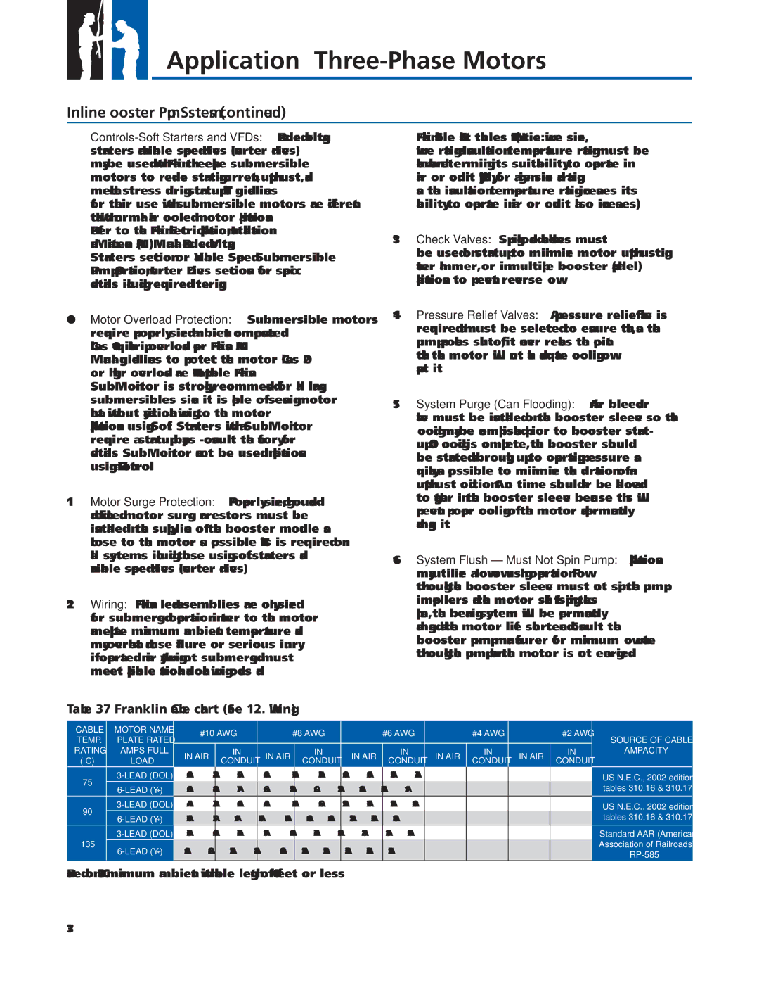
12.Wiring: Franklin’s lead assemblies are only sized for submerged operation in water to the motor nameplate maximum ambient temperature and may overheat and cause failure or serious injury if operated in air. Any wiring not submerged must meet applicable national and local wiring codes and
Franklin Cable Chart tables
13.Check Valves:
14.Pressure Relief Valves: A pressure relief valve is required and must be selected to ensure that, as the pump approaches
15.System Purge (Can Flooding): An air bleeder valve must be installed on the booster sleeve so that fl ooding may be accomplished prior to booster start- up. Once fl ooding is complete, the booster should be started and brought up to operating pressure as quickly as possible to minimize the duration of an upthrust condition. At no time should air be allowed to gather in the booster sleeve because this will prevent proper cooling of the motor and permanently damage it.
16.System Flush – Must Not Spin Pump: Applications may utilize a low fl ow fl ushing operation. Flow through the booster sleeve must not spin the pump impellers and the motor shaft. If spinning takes place, the bearing system will be permanently damaged and the motor life shortened. Consult the booster pump manufacturer for maximum fl ow rate through the pump when the motor is not energized.
Table 37 Franklin Cable chart (See 12. Wiring)
CABLE | MOTOR NAME- | |
TEMP. | PLATE RATED | |
RATING | AMPS FULL | |
(°C) | LOAD | |
75 | ||
| ||
90 | ||
| ||
| ||
135 | ||
|
#10 AWG |
| #8 AWG | #6 AWG | #4 AWG | #2 AWG | ||||||
IN AIR | IN | IN AIR | IN | IN AIR | IN | IN AIR | IN | IN AIR | IN | ||
CONDUIT | CONDUIT | CONDUIT | CONDUIT | CONDUIT | |||||||
|
|
|
|
|
| ||||||
40A | 28A | 56A |
| 40A | 76A | 52A | 100A | 68A | 136A | 92A | |
69A | 48A | 97A |
| 69A | 132A | 90A | 173A | 118A | 236A | 19A | |
|
|
|
|
|
|
|
|
|
|
| |
44A | 32A | 64A |
| 44A | 84A | 60A | 112A | 76A | 152A | 104A | |
76A | 55A | 111A |
| 76A | 145A | 104A | 194A | 132A | 263A | 180A | |
|
|
|
|
|
|
|
|
|
|
| |
63A | 46A | 74A |
| 51A | 104A | 74A | 145A | 98A | 185A | 126A | |
109A | 80A | 127A |
| 88A | 180A | 129A | 251A | 320A | 320A | 219A | |
|
|
|
|
|
|
|
|
|
|
| |
SOURCE OF CABLE
AMPACITY
US N.E.C., 2002 edition, tables 310.16 & 310.17
US N.E.C., 2002 edition, tables 310.16 & 310.17
Standard AAR (American
Association of Railroads)
Based on 30 °C maximum ambient with cable length of 100 feet or less.
37