Application – Three-Phase Motors
Inline Booster Pump Systems (continued)
Design And Operational Requirements
1.
2.Motor, Sleeve, and Pump Support System: The booster sleeve ID must be sized according to the motor cooling and pump NPSHR requirements. The support system must support the motor’s weight, prevent motor rotation and keep the motor and pump aligned. The support system must also allow for thermal axial expansion of the motor without creating binding forces.
3.Motor Support Points: A minimum of two support points are required on the motor. One in the motor/ pump fl ange connection area and one in the bottom end of the motor area. The motor castings, not the shell area, are recommended as support points. If the support is a full length support and/or has bands in the shell area, they must not restrict heat transfer or deform the shell.
4.Motor Support Material and Design: The support system shall not create any areas of cavitation or other areas of reduced fl ow less than the minimum rate required by this manual. They should also be designed to minimize turbulence and vibration and provide stable alignment. The support materials and locations must not inhibit the heat transfer away from the motor.
5.Motor and Pump Alignment: The maximum allowable misalignment between the motor, pump, and pump discharge is 0.025 inch per 12 inches of length (2 mm per 1000 mm of length). This must be measured in both directions along the assembly using the motor/pump fl ange connection as the starting point. The booster sleeve and support system must be rigid enough to maintain this alignment during assembly, shipping, operation and maintenance.
6.The best motor lubrication and heat resistance is obtained with the factory based propylene glycol
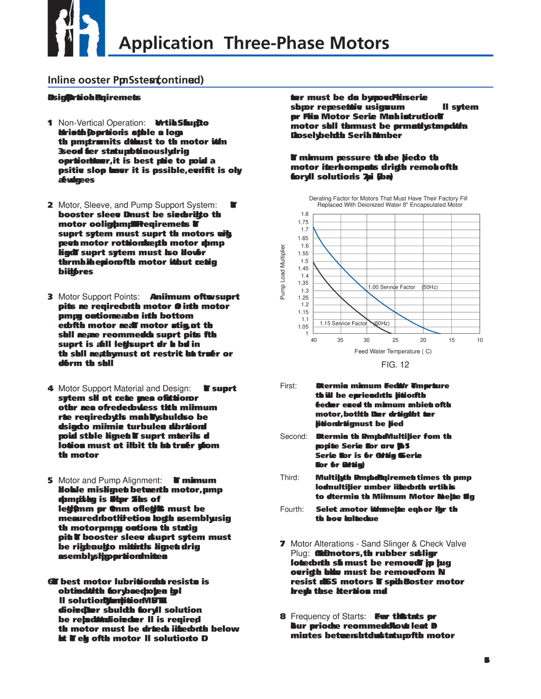
fi ll solution. Only when an application MUST HAVE deionized (DI) water should the factory fi ll solution be replaced. When a deionized water fi ll is required, the motor must be derated as indicated on the below chart. The exchange of the motor fi ll solution to DI
water must be done by an approved Franklin service shop or representative using a vacuum fill system per Franklin’s Motor Service Manual instruction. The motor shell then must be permanently stamped with a D closely behind the Serial Number.
The maximum pressure that can be applied to the motor internal components during the removal of the factory fi ll solution is 7 psi (0.5 bar.)
Derating Factor for Motors That Must Have Their Factory Fill Replaced With Deionized Water 8" Encapsulated Motor
| 1.8 |
|
|
|
|
|
|
|
|
|
|
|
|
| 1.75 |
|
|
|
|
|
|
|
|
|
|
|
|
|
|
|
|
|
|
|
|
|
|
|
|
| |
| 1.7 |
|
|
|
|
|
|
|
|
|
|
|
|
|
|
|
|
|
|
|
|
|
|
|
|
| |
Multiplier | 1.65 |
|
|
|
|
|
|
|
|
|
|
|
|
|
|
|
|
|
|
|
|
|
|
|
| ||
1.6 |
|
|
|
|
|
|
|
|
|
|
|
| |
|
|
|
|
|
|
|
|
|
|
|
|
| |
| 1.55 |
|
|
|
|
|
|
|
|
|
|
|
|
|
|
|
|
|
|
|
|
|
|
|
|
| |
| 1.5 |
|
|
|
|
|
|
|
|
|
|
|
|
|
|
|
|
|
|
|
|
|
|
|
|
| |
Load | 1.45 |
|
|
|
|
|
|
|
|
|
|
|
|
|
|
|
|
|
|
|
|
|
|
|
| ||
1.4 |
|
|
|
|
|
|
|
|
|
|
|
| |
|
|
|
|
|
|
|
|
|
|
|
|
| |
Pump | 1.35 |
|
|
|
|
|
|
|
|
|
|
|
|
|
|
| 1.00 Service | Factor |
| (50Hz) |
|
|
|
| |||
1.25 |
|
|
|
|
|
|
|
| |||||
| 1.3 |
|
|
|
|
|
|
|
|
|
|
|
|
| 1.2 |
|
|
|
|
|
|
|
|
|
|
|
|
|
|
|
|
|
|
|
|
|
|
|
|
| |
| 1.15 |
|
|
|
|
|
|
|
|
|
|
|
|
|
|
|
|
|
|
|
|
|
|
|
|
| |
| 1.1 |
|
|
|
|
|
|
|
|
|
|
|
|
|
| 1.15 Service Factor |
| (60Hz) |
|
|
|
|
|
|
| ||
| 1.05 |
|
|
|
|
|
|
|
|
| |||
|
|
|
|
|
|
|
|
|
|
|
|
| |
| 1 |
|
|
|
|
|
|
|
|
|
|
|
|
|
|
|
|
|
|
|
|
|
|
|
|
| |
| 40 | 35 | 30 | 25 | 20 | 15 | 10 | ||||||
Feed Water Temperature (°C)
FIG. 12
First: Determine maximum Feed Water Temperature that will be experienced in this application. If the feed water exceeds the maximum ambient of the motor, both the DI water derating and a hot water application derating must be applied.
Second: Determine the Pump Load Multiplier from the appropriate Service Factor curve. (Typical 1.15 Service Factor is for 60 Hz ratings &1.00 Service Factor for 50 Hz ratings).
Third: Multiply the Pump Load Requirement times the pump load multiplier number indicated on the vertical axis to determine the Minimum Motor Nameplate Rating.
Fourth: Select a motor with a nameplate equal or higher than the above calculated value.
7.Motor Alterations - Sand Slinger & Check Valve Plug: On 6" and 8" motors, the rubber sand slinger located on the shaft must be removed. The pipe plug covering the check valve must be removed from Ni- resist and 316 SS motors. The special Booster motor already has these alterations made.
8.Frequency of Starts: Fewer than 10 starts per
minutes between shutdown and
36