Application – Single-Phase Motors
Auxiliary Running Capacitors
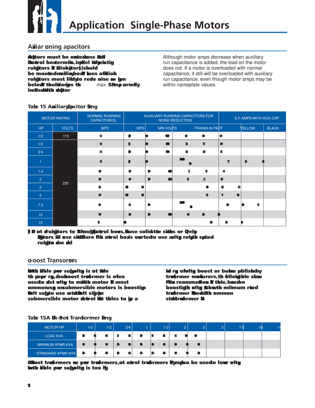
Added capacitors must be connected across “Red” and “Black” control box terminals, in parallel with any existing running capacitors. The additional capacitor(s) should be mounted in an auxiliary box. The values of additional running capacitors most likely to reduce noise are given below. The tabulation gives the max S.F. amps normally in each lead with the added capacitor.
Although motor amps decrease when auxiliary run capacitance is added, the load on the motor does not. If a motor is overloaded with normal capacitance, it still will be overloaded with auxiliary run capacitance, even though motor amps may be within nameplate values.
Table 15 Auxiliary Capacitor Sizing
MOTOR RATING | NORMAL RUNNING |
| AUXILIARY RUNNING CAPACITORS FOR | S.F. AMPS WITH RUN CAP |
| |||||
CAPACITOR(S) |
|
| NOISE REDUCTION |
| ||||||
|
|
|
|
|
|
|
| |||
HP | VOLTS | MFD | MFD |
| MIN VOLTS | FRANKLIN PART | YELLOW | BLACK | RED | |
1/2 | 115 | 0 | 60(1) |
| 370 | TWO 155327101 | 8.4 | 7.0 |
| 4.0 |
|
|
|
|
|
|
|
|
|
|
|
1/2 |
| 0 | 15(1) |
| 370 | ONE 155328101 | 4.2 | 3.5 |
| 2.0 |
3/4 |
| 0 | 20(1) |
| 370 | ONE 155328103 | 5.8 | 5.0 |
| 2.5 |
1 |
| 0 | 25(1) |
| 370 | ONE EA. 155328101 | 7.1 | 5.6 |
| 3.4 |
|
| 155328102 |
| |||||||
|
|
|
|
|
|
|
|
|
| |
1.5 |
| 10 | 20 |
| 370 | ONE 155328103 | 9.3 | 7.5 |
| 4.4 |
2 | 230 | 20 | 10 |
| 370 | ONE 155328102 | 11.2 | 9.2 |
| 3.8 |
3 | 45 | NONE |
| 370 |
| 17.0 | 12.6 |
| 6.0 | |
|
|
|
| |||||||
5 |
| 80 | NONE |
| 370 |
| 27.5 | 19.1 |
| 10.8 |
7.5 |
| 45 | 45 |
| 370 | ONE EA. 155327101 | 37.0 | 32.0 |
| 11.3 |
|
| 155328101 |
| |||||||
|
|
|
|
|
|
|
|
|
| |
10 |
| 70 | 30 |
| 370 | ONE 155327101 | 49.0 | 42.0 |
| 13.0 |
15 |
| 135 | NONE |
|
|
| 75.0 | 62.5 |
| 16.9 |
|
|
|
|
|
|
|
|
|
|
|
(1)Do not add running capacitors to 1/3 through 1 hp control boxes, which use solid state switches or QD relays. Adding capacitors will cause switch failure. If the control box is converted to use a voltage relay, the specifi ed running capacitance can be added.
Buck-Boost Transformers
When the available power supply voltage is not within the proper range, a
wide range of voltage boost or buck are published by transformer manufacturers, the following table shows Franklin’s recommendations. The table, based on boosting the voltage 10%, shows the minimum rated transformer kVA needed and the common standard transformer kVA.
Table 15A Buck-Boost Transformer Sizing
MOTOR HP
LOAD KVA
MINIMUM XFMR KVA
STANDARD XFMR KVA
1/3
1.02
0.11
0.25
1/2
1.36
0.14
0.25
3/4
1.84
0.19
0.25
1
2.21
0.22
0.25
1.5
2.65
0.27
0.50
2
3.04
0.31
0.50
3
3.91
0.40
0.50
5
6.33
0.64
0.75
7.5
9.66
0.97
1.00
10
11.70
1.20
1.50
15
16.60
1.70
2.00
15