Maintenance – Electronic Products
Pumptec-Plus
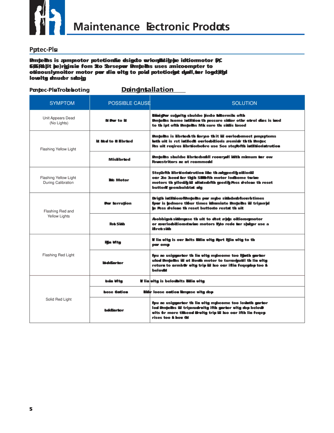
Pumptec-Plus – Troubleshooting During Installation
SYMPTOM
POSSIBLE CAUSE
SOLUTION
Unit Appears Dead |
| Check wiring. Power supply voltage should be applied to L1 and L2 terminals of the | |
No Power to Unit | |||
(No Lights) | |||
| to the input of the | ||
|
| ||
|
|
| |
|
| ||
| Unit Needs to Be Calibrated | when the unit is fi rst installed. This overload condition is a reminder that the Pumptec- | |
Flashing Yellow Light |
| Plus unit requires calibration before use. See step 7 of the installation instructions. | |
|
| ||
| Miscalibrated | ||
| Flow restrictors are not recommended. | ||
|
| ||
|
|
| |
|
| Step C of the calibration instructions indicate that a fl ashing green light condition will | |
Flashing Yellow Light | occur 2 to 3 seconds after taking the SNAPSHOT of the motor load. On some two wire | ||
During Calibration | motors the yellow light will fl ash instead of the green light. Press and release the reset | ||
| |||
|
| button. The green should start fl ashing. | |
|
|
| |
|
| During the installation of | |
| Power Interruption | If power is cycled more than four times within a minute | |
Flashing Red and |
| cycle. Press and release the reset button to restart the unit. | |
|
| ||
Yellow Lights |
| A bobbing fl oat switch may cause the unit to detect a rapid cycle condition on any motor | |
|
| ||
| Float Switch | or an overload condition on two wire motors. Try to reduce water splashing or use a | |
|
| different switch. | |
|
|
| |
| High Line Voltage | The line voltage is over 253 volts. Check line voltage. Report high line voltage to the | |
| power company. | ||
|
| ||
Flashing Red Light |
|
| |
| If you are using a generator the line voltage may become too high when the generator | ||
| Unloaded Generator | unloads. | |
| returns to normal. Over voltage trips will also occur if line frequency drops too far | ||
|
| ||
|
| below 60 Hz. | |
|
|
| |
| Low Line Voltage | The line voltage is below 207 volts. Check line voltage. | |
|
|
| |
| Loose Connections | Check for loose connections which may cause voltage drops. | |
Solid Red Light |
|
| |
| If you are using a generator the line voltage may become too low when the generator | ||
|
| ||
| Loaded Generator | loads. | |
| volts for more than 2.5 seconds. Undervoltage trips will also occur if the line frequency | ||
|
| ||
|
| rises too far above 60 Hz. | |
|
|
|
55