RC-1500-1T
Radio Rack Console
00080625900
Safety Instructions
Do not open the equipment
Table of Contents
This page is intentionally left blank
Part
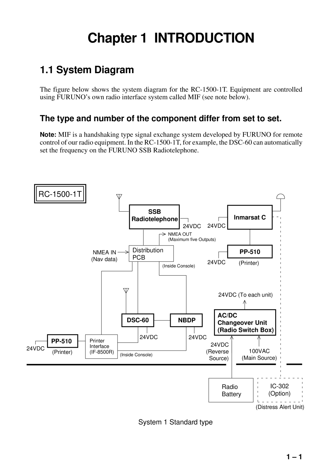
Introduction
Introduction
System 2 Dual Inmarsat C type
Equipment Description
Mutual Operation of Equipment
Power On/Off
This page is intentionally left blank
RC-1500-1T Control Panel and PP-510
Battery Charger switch
Battery charging
Maintenance
PP-510
Loading roll paper
Loading new roll paper
Paper Guide Bar Paper Release Lever Platen Knob Paper Baii
SSB Radiotelephone2
Part
MF/HF3DSC
Page
LOG File
Page
Foreword
Features
Program number
DSC Call
What is DSC?
Contents of a DSC call
Case of Accidental Trans Mission of the Distress Alert
Distress alert call and reply
Audio Alarms
Basic procedure
Individual call
Remote control
Remote Control and Automatic Acknowledge
Both remote control and automatic acknowledge on
Automatic acknowledge
Interpreting Call Displays
Receive calls
Distress call
Received message
Individual call
Distress Call in progress
Send calls
Remote Control of SSB Radiotelephone
SSB output power at transmission of distress alert
Keyboard lock at the SSB radiotelephone
This page is intentionally left blank
Controls, LED Description
Operational Overview
Control, LED description
Turning the Power On/Off
Radiotelephone setting screen
DSC standby screen
Panel Backlighting, LCD Contrast and Brightness
Loudspeaker, Buzzer On/Off
Starting, Stopping Scanning DSC Routine Frequencies
Press ACK
Automatic Acknowledge On/Off
Intercom On/Off
Selection of On-screen Items
Manual Entry of Position and Time
Enter UTC time and press the ENT key. The Setup menu appears
Remote Control of Furuno SSB Radiotelephone
Mode selection
Channel selection
Tx/Rx frequency selection
Power selection
Tuning
Sending distress alert by Distress button
Sending Distress Alert
Time to go until distress Alert transmission is completed
Menu
Sending distress alert with nature of distress specified
Press to select Manual and press the ENT key
Send
Follow steps 3-6 on page 3-2
Distress alert received on MF band
Receiving a Distress Alert
Continue
Procedure when distress alert is received
Sending the distress relay to a coast station
Send
Sending the distress acknowledge to ship in distress
Send message
Distress alert received on HF band
Coast ID
Sending distress relay to coast station
Sending Distress Relay on Behalf of a Ship in Distress
Press the ENT key to open the NATURE5menu
Call Type Relay SEL Coast ID
Sending distress relay to all ships
NBDP-FEC
COM Type Telephone DSC Freq
Receiving Distress Relay from Coast Station
Receiving Distress Relay All Ships from Ship
This page is intentionally left blank
Sending all ships call
All Ships Call
Press the ENT key to display the Priority menu Send message
Receiving all ships call
Sending individual call
Individual Call
To select a user channel
Routine or ships business priority
How to set working frequency
Channel
Safety or urgency priority
12 MHZ
How to set DSC frequency
Intl
Send
Able acknowledge call received
Unable acknowledge call received
No response! Try calling again?
Sending automatic acknowledge ACK BQ with comply type ABL E
Receiving individual call
Press the Call key to re-send the call
Call Type Individual
Manually acknowledging individual call with AB LE
Manually acknowledging individual call with Unable
Press the ENT key to open the Call Type menu Send message
Sending a group call
Group Call
To select a user channel
Send message
Receiving a group call
Sending a geographical area call
Geographical Area Call
Press the ENT key to open the Priority menu Send message
Press the ENT key to open the DSC Freq menu Send message
Receiving a geographical area call
Sending a neutral craft call
Neutral Craft Call
Receiving a neutral craft call
Sending a medical transport call
Medical Transport Call
Receiving a medical transport call
Sending a polling call
Polling Call
Routine
Polling acknowledge call received
Automatic reply
Receiving a polling call
Manual reply
Position Call
Sending own ships positionÅto other stations
Finding position of other station
Position call requesting other ship’s position
Display now looks something like the following Send message
Acknowledge call received
Position call other ship requests your position
ANSWER34ALL View
Pos acknowledge call in progress
Sending Pstn call, receiving acknowledge back ACK BQ
Pstn Call
Enter telephone no digits max. and press the ENT key
Waiting for acknowledgement
Unable acknowledge
Pressing the 8/PRINT key
Unable acknowledge call received
Waiting for acknowledge
Unable to acknowledge call received
Receiving Pstn call, sending acknowledge back ACK BQ
One of the following messages appears
No response! charge information
Charge Information Charge Time no Info
Log File Description
Opening a Log File
Distress log
Select file
Ordinary log
Transmitted log
Preparing Individual Call Messages
Preparing Send Messages
Messag
How to Enter File Name and Number
Preparing Group Call Messages
Preparing Geographical Area Call Messages
Message
000000000
Preparing Pstn Call Messages
Preparing Test Call Messages
Furuno Japan
Sending Prepared Messages
Printing List of Send Message Files
Setup Menu Overview
Setup Menu
Alarm setup
Alarm Menu
Auto Ack Menu
Auto ack setup
Message Menu
Erase File Menu
Print Out Menu
Position Menu
Received message at JAN-08-1999-161012
Sample printouts
Distress frequencies
Scan Freq Menu
Routine frequencies
User CH Menu
01234
Volume setup
Volume Menu
System Menu
Test Menu
This page is intentionally left blank
Daily Test
CHECKING, Maintenance
Maintenance
Preventive maintenance
Cleaning
Error Messages
Simple Troubleshooting
Test Call
Test acknowledge received
Test acknowledge call received
Menu Tree
Appendix
Tx kHz Rx kHz Remarks File Name
DSC Frequency Table
DSC Regulations
This page is intentionally left blank
4NBDP
Page
Foreword Radiotelex Communication
Page
Foreword
Features
This page is intentionally left blank
General
Code Description
Frequency Shift
ARQ Mode A-Mode
Description
Traffic Exchange Sequence
Termination of Communication
ARQ mode traffic exchange timing
Initiating a Call
FEC Mode B-Mode
System Overview
System Configuration
Turning on the System
Equipment Description
Terminal Unit
Printer option
Main Unit
Function Keys, Menu Operation
Menu Conventions
Basic Menu Operation
Selecting menu items and options
Function Key Description
Undo
Call Station
Display Nmea Data
Station Entry
Setup
MIF AGC
Function key F10 Break
Registering Answerback Code
Registering Answerback Code & ID Codes
Message for confirmation of code entered
Registering ID Codes
Registering Stations
Station List
Editing/Deleting Stations
OK/CANCEL prompt
Registering Timer Programs
Timer Programming
Editing/Deleting Timer Programs
Registering Scan Channel Groups
Scan Channel Groups
Editing/Deleting Scan Channel Groups
Registering User Channels
User Channels
Editing/Deleting User Channels
Creating Files
File Operations
Saving a File
Saving a File
Cutting and Pasting Text
Editing Files
Clearing the Paste Buffer
Copying and Pasting Text
Undo
Select All
Searching Text
Cut and paste flow diagram
Goto Line
Replacing Text
Switching Between Files
Opening Files
Opening a File
Renaming Files
Saving a File Under a New Name
Deleting Files
Printing Files
Real Time Printing
Communications Log
Displaying the Communications Log Log File
Printing the Log File
Manual Calling
TRANSMISSION, Reception
Manual calling screen
Calling a Station
Selecting Receive Mode
Transmitting a File from a Floppy Disk
Stopping Transmission
Con Nect
ARQ Mode Operation
Send a file from a floppy disk
FEC Mode Operation
Communication Example
Registration procedure
Transmitting message directly Dirtlx
Table of Abbreviations
Timer Operation
Enabling Timer Operation
Stopping Timer Operation
Communication Buffer
Scanning
Display Nmea Data
Window Menu Description
Calendar
Remote A, Remote B
Distress Frequency Table
Maritex Operation
What is MARITEX?
Preparations for Transmission
Maritex Services
Registering Scan Groups
MARITEX-A
Maritex Channel
ARQ FEC Dirc
Scanning group list example
Preparing Programs for Automatic Message Transmission
Commands
Maritex Traffic Manual
Store-and-Forward Telex
No. Procedure DisplayRemarks
Preparing a macrofile for store-and-forward Telex
Save prompt
Example macrofile for direct dialing
Macrofile for Direct Dialing
Procedure for direct dialing
Example of macrofile for use in multi address
Macrofile for Multi Address
10 Example of macrofile for semi-fax
Macrofile for Semi-fax
Transmitting in Maritex System
Basic Procedure
Press the 2 key. The Call Macro screen appears
Actual Transmission
Cleaning the Equipment
Maintenance
Connectors and Earth Connection
Floppy Disk Drive
Diagnostic Tests
Simple Troubleshooting
Power Supply
Self Test
Tone test 1 All characters
Tone Test
Tone test 5 Space
Appendix 1 ITU Telex CHANNELS/ Frequency List
AP1-2
AP1-3
AP1-4
Appendix 2 International Telex Abbreviations
This page is intentionally left blank
Inmarsat5C
Page
Contents
System Initialization
INMARSAT-C Communications
Page
Menu Tree
Operational Overview
Introduction
Foreword
Features
Distress Alert
About This Manual
Felcom 12 system configuration
Felcom 12 System Configuration
INMARSAT-C System
Inmarsat-C satellite communication system
Inmarsat System Configuration
Inmarsat system satellites
Page
NCS common channel
Communications Network
MES interface
Types of MES
Distress/Urgent Receiving Unit IC-303
Peripheral Equipment
Distress Alert Unit IC-302
Distress Message Controller DMC-5Option
This page is intentionally left blank
Communication Unit
When the audible alarm sounds
Floppy disk
Terminal Unit
Printer PP-510
Printer PP-510 optional supply
Key description
Keyboard
Alt
Shortcut key operation
Function Menus
Function menu description
Selecting menu, menu options
Standby display
Sample menu operation
Communication network mode
Display Indications
Distress alert information
Communication unit remarks and DCE version number
Communication unit status
Frame synchronization
Ocean region receiving
Logging status
Error Messages and Alerts
Other information
Date and time display
Silencing the alarm by the Setup menu
Silencing the Audible Alarm
Using a Personal Computer as a Terminal Unit
Installing the program
PC requirements
Contents of program disk
Two sets of DTEs installed
System Settings
Press 2 to display the System Setup screen
System setup
System setup menu, preferred NCS
System setup menu, nav port
11 System setup menu, message output port
Press Esc to open the update window
Terminal Setup
Login and Logout
15 Options menu
Login
Logout
17 Appearance of display screen during login
18 Options menu, logout screen
What is the EGC Enhanced Group Call service?
EGC Settings
Distress Alert Setup
EGC setup
22 EGC setup screen, Navarea window
24 EGC setup screen, waypoint
Programming EGC channels
26 EGC setup screen, update window
28 EGC channel list, cursor displayed
Programming NCS Channels
30 NCS channel list
Programming the LES list
LES List Operations
35 LES list, LES entry window
Printing the LES list
Deleting and changing the LES list
LES IDs
Programming the station list
Station List Operations
41 Selection window for destination type
Prefix Code Function
Printing the station list
Editing the station list
44 Ship position
Entering Own Ship’s Position
Comtest
Setting Directories
Press 5 to display the E-mail Service List
Mail Service List
53 Service station list
AOR.W AOR.E POR IOR
Mail Setup
Press Enter to the update window
This page is intentionally left blank
Preparing a routine message
Preparing a Message
Preparing a confidential message
Explanation of addressee code and password
Editor setup menu
Editor menu setup
Appearance of highlighted text
10 Cursor selects location where to paste text
Search and Replace
Insert with Citation
Go to line
Time or Pos. ins
Formatting a floppy disk
Saving a Message
Save message, retain place on screen
Saving a message
Save message, clear screen
18 Internal memory
Opening a File
20 How the change window feature works
Opening a file where a working area is occupied
23 Save screen, prompt for saving a message before closing
25 Save screen, overwrite file name
Printing a File
Deleting a File
Combining Files
28 Prompt for verification of file delete
Mime Multipurpose Internet Mail Extensions
30 File, rename
Rename
Code description
Transmitting
Message, subscriber destination and code
Transmitting prepared message
Transmit message menu, destination type window
Transmit message menu, country/ocean code window
Transmit message menu, station ID window opened
Transmit message menu, address window
Procedure for transmitting a message con’t from
11 Transmit message menu, option window opened
Transmitting message stored on floppy disk multiple address
Transmit Message Status
12 Transmit menu
15 Select station screen
17 LES list
20 Sample cancel screen
Canceling transmission
Confirming delivery status message status list
21 Cancel window
Message status list description
24 Request delivery status display
Manually requesting delivery status
26 Transmit message menu
2-digit code services
For maritime safety service
27 Transmit message menu, FAX selected
Inserting the destinations of a fax terminal
Receiving
When a message is received
Display log
Setting the receive alarm
29 Sample display message screen
Displaying receive messages
30 Sample receive message
Printing receive messages
Automatically saving receive messages
Saving receive messages to a floppy disk
35 Sample delete message screen
Deleting receive messages
Display Log
Distress/Urgent Receiving Call Unit IC-303
Displaying and printing the display log
Display log description
Automatic printing of display log
EGC Messages
Display send message log or receive message log
Displaying and reprinting EGC messages
40 EGC network ID list
Displaying EGC closed network ID Enid
Receiving EGC distress or urgent message
Data Reporting
Setting a data report
Data report menu
Select Yes Press Enter to close the Data Report window
Message report menu
Setting a message report
Page
Polling
Polling command
Polling reception
Polling command on MES message channel
Displaying Dnid
Dnid Data Network Identification
Enabling/Disabling Dnid
This page is intentionally left blank
Preparing a Distress Alert
Distress Alert
Distress Alert setup, requesting confirmation of settings
Distress Alert Unit IC-302
Transmitting a Distress Alert
Test Menu
Testing Distress Button
Sample distress message
Distress Communications
Transmit message screen with send start confirmation prompt
Aborting an Operation
Other Functions
Ocean region screen
Scanning NCS
EGC channel list screen
Selecting EGC Receiving Channel
NCS channel list
Selecting NCS Channel
Safety Information
Maintenance
Cleaning the terminal unit and communication unit
General Checking and Maintenance
Checking connectors and earth terminal
When the power can’t be turned on power lamp does not light
Self test at power application communication unit
Testing the communication unit through the keyboard
Self Tests
PV test sequence
Performance Verification PV Test
PV test screen
PV test procedure
Date and time of test
Results of PV test
System status monitor display
System Status Monitor
Waypoint
Interpreting the system status monitor
Replacing Internal Battery
This page is intentionally left blank
Appendix
International Telex/Telephone Country Code List
Page
Page
Page
Page
Page
Page
Page
Abbreviation Meaning
International Telex Abbreviations
Acronym Meaning
Glossary of Acronyms
International Telegraphy Alphabet
You input an invalid LES ID
You need to insert a floppy disk into the drive
This message will appear if the communi
LES IDs List
This page is intentionally left blank
Specifications of the Gmdss Radio Rack Console
Specifications of the SSB Radiotelephone FS-1562-25
Power AMP Unit
Specifications of FS-5000 SSB Radiotelephone
Relative Humidity 93% max. at 35C
Specifications of the DSC/WATCH Receiver DSC-60
O Data
Specifications of the Nbdp Terminal DP-6
Specifications of the Inmarsat MES Felcom
Specifications of the Printer PP-510
Battery Charger BC-6158