IGNITION
INTERMITTENT
PILOT IGNITOR
I
INTERMITTENT PILOT IGNITOR
MODULE 3 VAC
S
TRANSFORMER 3V |
|
| WHITE |
|
|
|
| ORG |
|
|
|
| GROUND TO |
|
| BROWN | FIREPLACE CHASSIS | ||
BLACK |
|
|
| |
BROWN |
|
| GREEN | |
RED |
| ORG | ||
|
|
|
| |
BATTERY PACK
TRANSFORMER
3VAC
REMOTE RECEIVER
IGNITION MODULE 3 VAC
| WHITE | |
| ORG | |
BLACK | GROUND TO | |
FIREPLACE CHASSIS | ||
| ||
RED |
|
TEMP SENSOR | VALVE |
THERMOSTAT WIRE ASSEMBLY
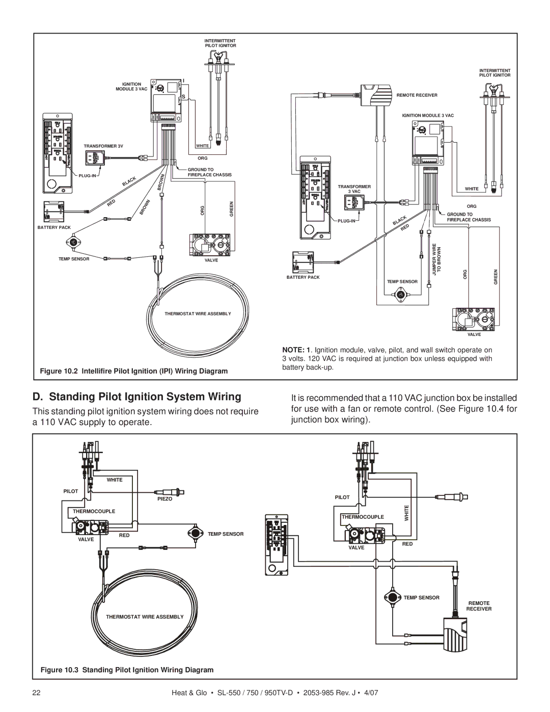
Figure 10.2 Intellifire Pilot Ignition (IPI) Wiring Diagram
TEMP SENSOR | JUMPER WIRE TO BROWN | ORG | GREEN |
BATTERY PACK |
|
|
|
VALVE
NOTE: 1. Ignition module, valve, pilot, and wall switch operate on 3 volts. 120 VAC is required at junction box unless equipped with battery
D. Standing Pilot Ignition System Wiring
This standing pilot ignition system wiring does not require a 110 VAC supply to operate.
It is recommended that a 110 VAC junction box be installed for use with a fan or remote control. (See Figure 10.4 for junction box wiring).
| WHITE |
|
|
|
PILOT |
|
| PILOT |
|
|
| PIEZO |
| |
THERMOCOUPLE |
| THERMOCOUPLE | WHITE | |
|
|
| ||
| RED | TEMP SENSOR |
|
|
VALVE |
|
| RED | |
|
|
| VALVE | |
|
|
|
| |
|
|
|
| TEMP SENSOR |
|
|
|
| REMOTE |
|
|
|
| RECEIVER |
| THERMOSTAT WIRE ASSEMBLY |
|
| |
Figure 10.3 | Standing Pilot Ignition Wiring Diagram |
|
| |
22 |
| Heat & Glo • |
| |