1. Control Board Layout
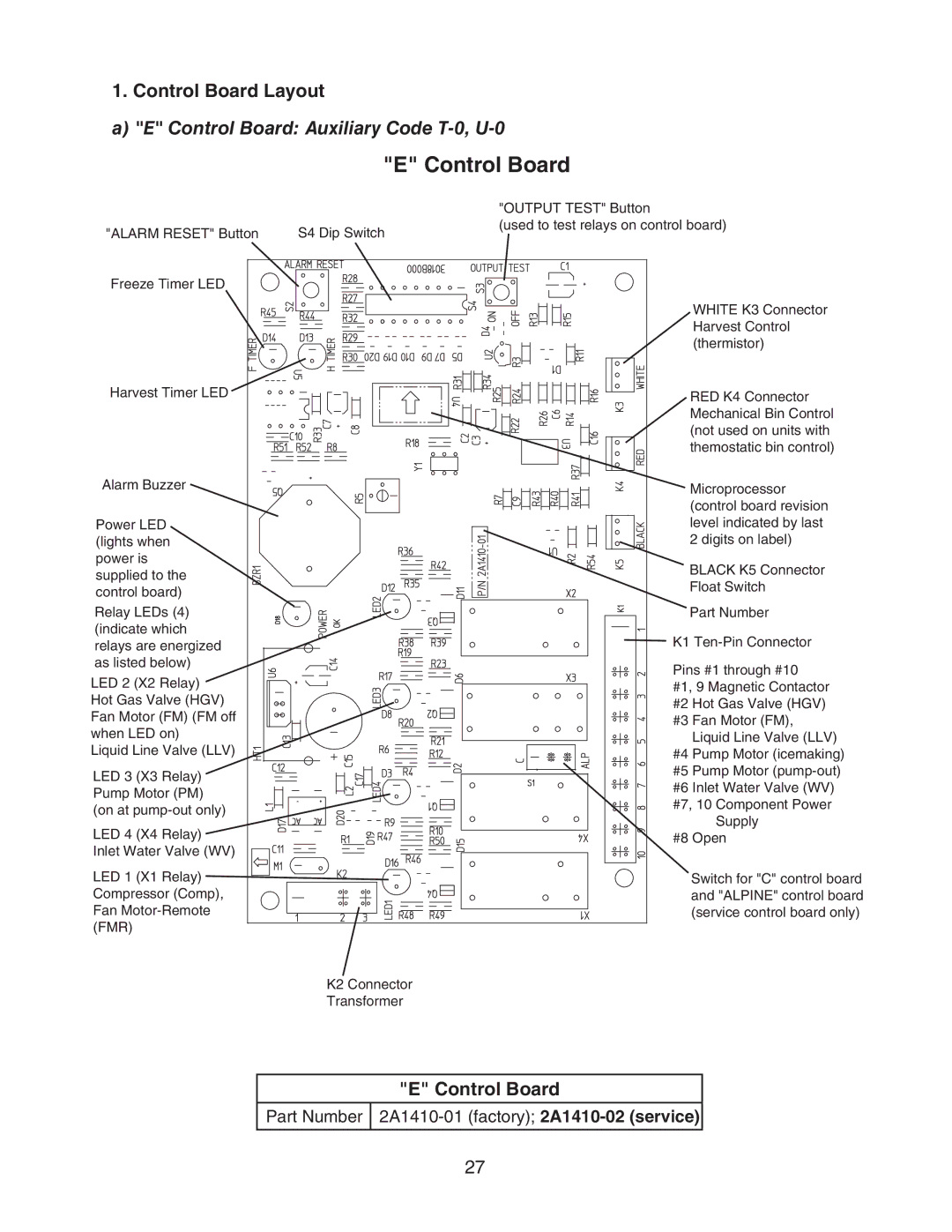
a) "E" Control Board: Auxiliary Code T-0, U-0
| "E" Control Board | |
|
| "OUTPUT TEST" Button |
"ALARM RESET" Button | S4 Dip Switch | (used to test relays on control board) |
| ||
Freeze Timer LED |
|
|
|
| WHITE K3 Connector |
|
| Harvest Control |
|
| (thermistor) |
Harvest Timer LED |
| RED K4 Connector |
|
| |
|
| Mechanical Bin Control |
|
| (not used on units with |
|
| themostatic bin control) |
Alarm Buzzer |
| Microprocessor |
|
| |
|
| (control board revision |
Power LED |
| level indicated by last |
(lights when |
| 2 digits on label) |
power is |
| BLACK K5 Connector |
supplied to the |
| |
| Float Switch | |
control board) |
| |
|
| |
Relay LEDs (4) |
| Part Number |
(indicate which |
| K1 |
relays are energized |
| |
as listed below) |
| Pins #1 through #10 |
LED 2 (X2 Relay) |
| |
| #1, 9 Magnetic Contactor | |
Hot Gas Valve (HGV) |
| #2 Hot Gas Valve (HGV) |
Fan Motor (FM) (FM off |
| #3 Fan Motor (FM), |
when LED on) |
| Liquid Line Valve (LLV) |
Liquid Line Valve (LLV) |
| #4 Pump Motor (icemaking) |
LED 3 (X3 Relay) |
| #5 Pump Motor |
| #6 Inlet Water Valve (WV) | |
Pump Motor (PM) |
| |
| #7, 10 Component Power | |
(on at |
| |
| Supply | |
LED 4 (X4 Relay) |
| |
| #8 Open | |
Inlet Water Valve (WV) |
|
|
LED 1 (X1 Relay) |
| Switch for "C" control board |
Compressor (Comp), |
| and "ALPINE" control board |
Fan |
| (service control board only) |
(FMR) |
|
|
| K2 Connector |
|
| Transformer |
|
"E" Control Board
Part Number
27