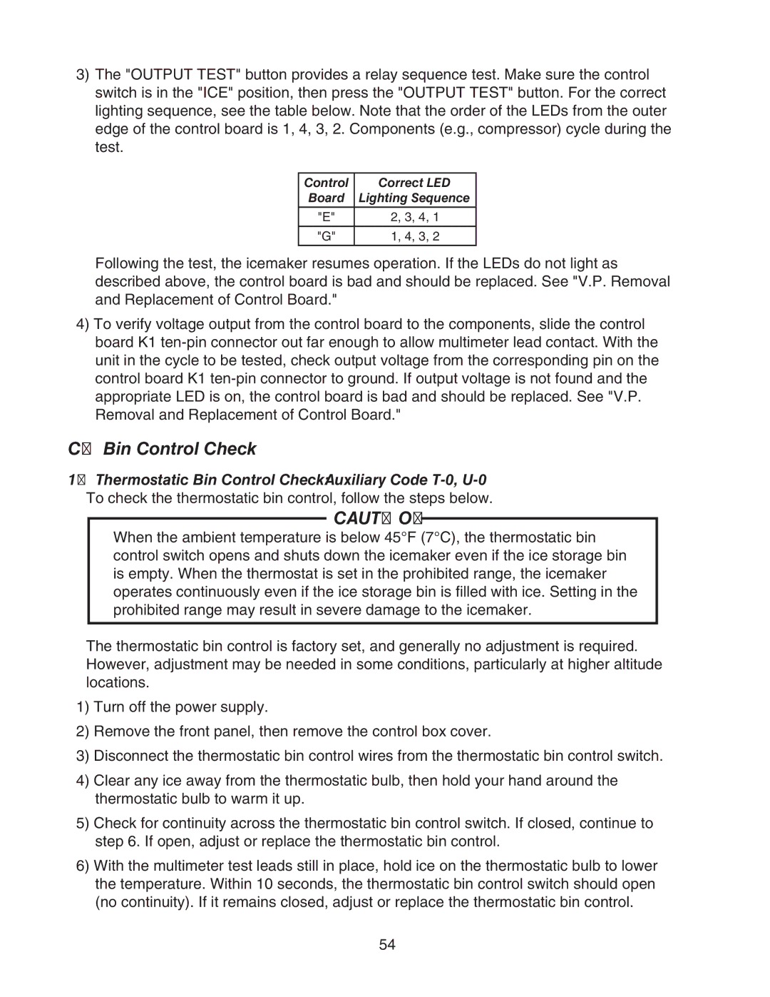
3)The "OUTPUT TEST" button provides a relay sequence test. Make sure the control switch is in the "ICE" position, then press the "OUTPUT TEST" button. For the correct lighting sequence, see the table below. Note that the order of the LEDs from the outer edge of the control board is 1, 4, 3, 2. Components (e.g., compressor) cycle during the test.
Control | Correct LED |
Board | Lighting Sequence |
|
|
"E" | 2, 3, 4, 1 |
|
|
"G" | 1, 4, 3, 2 |
Following the test, the icemaker resumes operation. If the LEDs do not light as described above, the control board is bad and should be replaced. See "V.P. Removal and Replacement of Control Board."
4)To verify voltage output from the control board to the components, slide the control board K1 ten‑pin connector out far enough to allow multimeter lead contact. With the unit in the cycle to be tested, check output voltage from the corresponding pin on the control board K1 ten‑pin connector to ground. If output voltage is not found and the appropriate LED is on, the control board is bad and should be replaced. See "V.P. Removal and Replacement of Control Board."
C.Bin Control Check
1.Thermostatic Bin Control Check: Auxiliary Code
CAUTION
When the ambient temperature is below 45°F (7°C), the thermostatic bin control switch opens and shuts down the icemaker even if the ice storage bin is empty. When the thermostat is set in the prohibited range, the icemaker operates continuously even if the ice storage bin is filled with ice. Setting in the prohibited range may result in severe damage to the icemaker.
The thermostatic bin control is factory set, and generally no adjustment is required. However, adjustment may be needed in some conditions, particularly at higher altitude locations.
1)Turn off the power supply.
2)Remove the front panel, then remove the control box cover.
3)Disconnect the thermostatic bin control wires from the thermostatic bin control switch.
4)Clear any ice away from the thermostatic bulb, then hold your hand around the thermostatic bulb to warm it up.
5)Check for continuity across the thermostatic bin control switch. If closed, continue to step 6. If open, adjust or replace the thermostatic bin control.
6)With the multimeter test leads still in place, hold ice on the thermostatic bulb to lower the temperature. Within 10 seconds, the thermostatic bin control switch should open (no continuity). If it remains closed, adjust or replace the thermostatic bin control.
54
