Preparing for Use
To install the HP 16500L interface module
5Slide the interface module into the mainframe through the slot in the rear panel.
6Install the screws connecting the interface module to the mainframe.
Two screws through the top of the interface module connect it to the sheetmetal plate, and four screws through the rear plate of the interface module connect it to the rear panel of the mainframe.
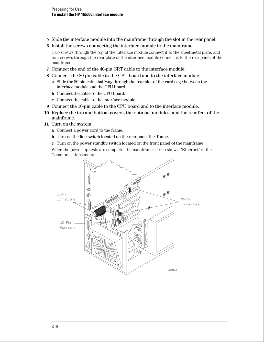
7Connect the end of the
8Connect the
a Slide the
b Connect the cable to the CPU board.
c Connect the cable to the interface module.
9Connect the
10Replace the top and bottom covers, the optional modules, and the rear feet of the mainframe.
11Turn on the system.
a Connect a power cord to the frame.
b Turn on the line switch located on the rear panel the frame.
c Turn on the power standby switch located on the front panel of the mainframe.
When the