Calibrating and Adjusting
To prepare the instrument
To prepare the instrument
1Remove the rear feet and the covers from the mainframe.
2Before starting the adjustments, mark the position where the potentiometers are set.
This helps in returning the adjustments to their original positions if it becomes necessary to restart the procedure.
3During any of the following CRT adjustments, the CRT module must face west.
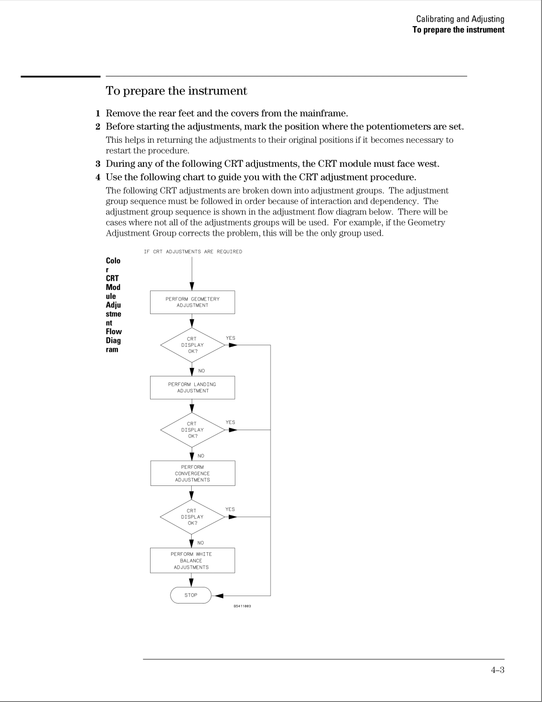
4Use the following chart to guide you with the CRT adjustment procedure.
The following CRT adjustments are broken down into adjustment groups. The adjustment group sequence must be followed in order because of interaction and dependency. The adjustment group sequence is shown in the adjustment flow diagram below. There will be cases where not all of the adjustments groups will be used. For example, if the Geometry Adjustment Group corrects the problem, this will be the only group used.
Colo r
CRT Mod ule Adju stme nt Flow Diag ram
