Calibrating and Adjusting
To adjust geometry
To adjust geometry
1Display the white cross-hatch test pattern on the CRT.
From the Color Display Test menu, select the white,
2Preset the front panel brightness control, the top of the two controls to the left of the display, maximum clockwise.
3Preset the front panel contrast control, the bottom of the two controls to the left of the display, to the mechanical center.
4Preset H.SUB SHIFT (RV006) and V.SUB SHIFT (RV008), located on the bottom PC board, to the mechanical centers.
All of the following adjustment potentiometers are located on the PC board on the left side of the display.
5Adjust the display size. Measure with a flexible ruler.
•Adjust H.SIZE (RV504) for a 161 mm (6.34 in.) width.
•Adjust V.HEIGHT (RV50) for a 120.5 mm (4.74 in.) height.
6Center the pattern.
•Adjust V.CENT (RV510) for vertical centering.
•Adjust H.CENT (RV503) for horizontal centering.
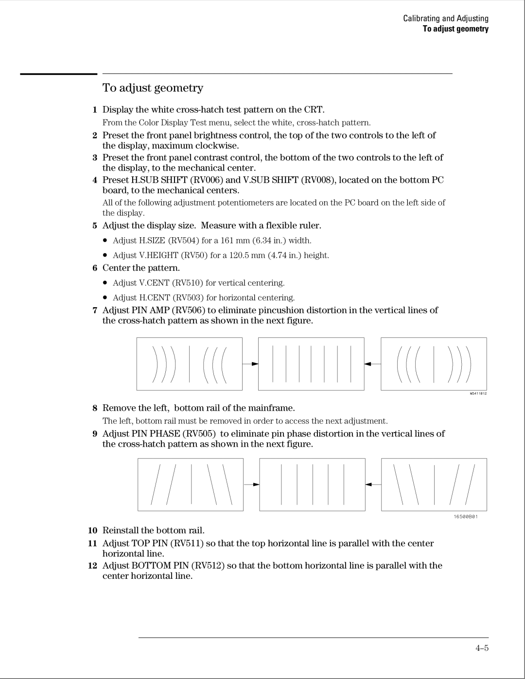
7Adjust PIN AMP (RV506) to eliminate pincushion distortion in the vertical lines of the
8Remove the left, bottom rail of the mainframe.
The left, bottom rail must be removed in order to access the next adjustment.
9Adjust PIN PHASE (RV505) to eliminate pin phase distortion in the vertical lines of the
10Reinstall the bottom rail.
11Adjust TOP PIN (RV511) so that the top horizontal line is parallel with the center horizontal line.
12Adjust BOTTOM PIN (RV512) so that the bottom horizontal line is parallel with the center horizontal line.