Troubleshooting
To test the expansion frame interface
Test the Expansion Interface Card
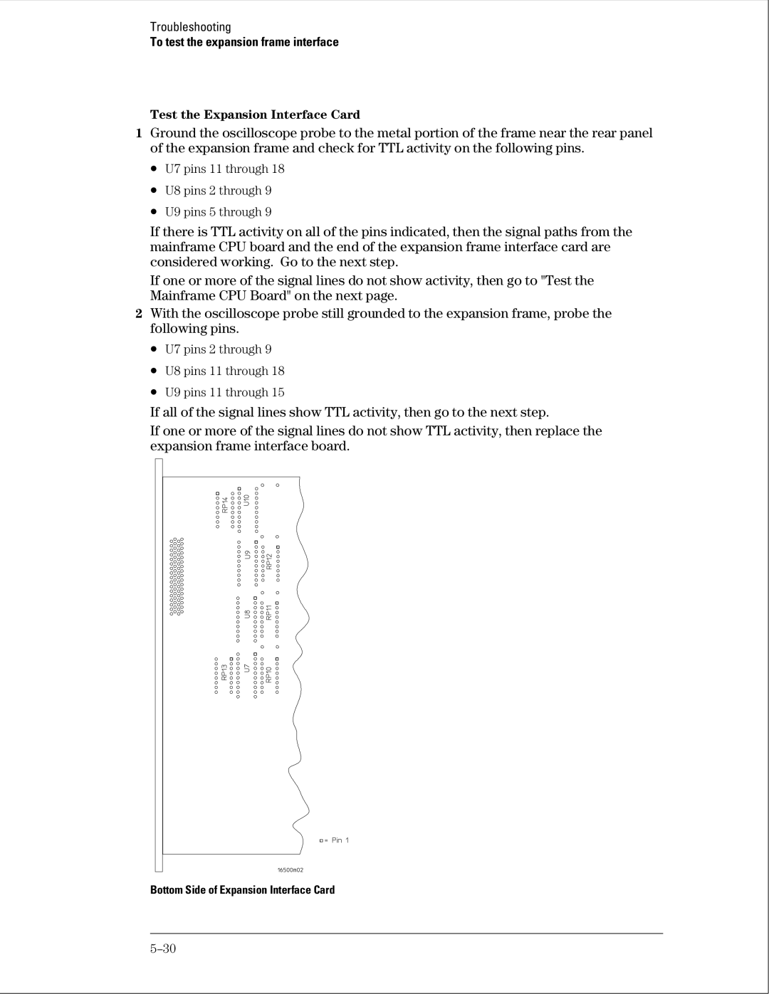
1Ground the oscilloscope probe to the metal portion of the frame near the rear panel of the expansion frame and check for TTL activity on the following pins.
•U7 pins 11 through 18
•U8 pins 2 through 9
•U9 pins 5 through 9
If there is TTL activity on all of the pins indicated, then the signal paths from the mainframe CPU board and the end of the expansion frame interface card are considered working. Go to the next step.
If one or more of the signal lines do not show activity, then go to "Test the Mainframe CPU Board" on the next page.
2With the oscilloscope probe still grounded to the expansion frame, probe the following pins.
•U7 pins 2 through 9
•U8 pins 11 through 18
•U9 pins 11 through 15
If all of the signal lines show TTL activity, then go to the next step.
If one or more of the signal lines do not show TTL activity, then replace the expansion frame interface board.
Bottom Side of Expansion Interface Card